|
|
|
|
|

|
|
Crypto AG Data BND CIA HC-500 series →
Portable off-line cipher machine · CRYPTOMATIC
HC-520 is a portable electronic off-line cipher machine
for text-based messages, introduced in 1977 by
Crypto AG (Hagelin) in Zug (Switzerland).
It is part of the HC-500 CRYPTOMATIC family,
which was the successor to the H-460 —
the first electronic cipher machine made by
Crypto AG.
The HC-520 is often seen as a modern electronic alternative to the
portable mechanical CD-57.
The device was developed by Siemens
and uses an NSA-developed
cryptographic algorithm [7].
|
The device measures 245 x 129 x 44 mm and weighs 976 grams (batteries not
included). It is powered by a 6V battery pack
– installed behind the display – or by an external adapter
which can be attached to a
recessed DB9 socket at the rear.
User interaction is via a 38-button rubber keypad and an 11-digit
alphanumeric LCD display that is divided into three sectors. The image on
the right shows the civil variant of the HC-520, which has a cream upper
case shell. It was also available in (military) green, but apart from the colour,
both variants are believed to be identical.
|
|
|
|
The cryptographic algorithm is implemented entirely in software,
and uses proprietary non-linear functions.
Although on other Cryptomatic devices
— such as the HC-550 —
this software runs on a general purpose Motorola 6800 microprocessor,
the HC-520 is built around an ultra low-power
12-bit DEC PDP-8 compatible CPU, with 6Kb of RAM
and the firmware stored in masked ROMs.
At least two versions of the firmware are known 1 and
variants
were made for different customers.
|
Text encrypted on the HC-520 was readable 2 to the NSA.
The HC-520 was developed between 1975 and 1977 – at a time when Crypto AG was
jointly owned by the BND
and the CIA – and was intended as a
competitor to the unreadable 3 Gretacoder 905
of the Swiss competitor Gretag.
It was hoped that customers would prefer the (readable) HC-520.
The device was in production until at least 1981, during which time
~ 700 units were made [2]. Many of them
were sold to South-American countries like Argentina [7].
The introduction price was 5000 Swiss Francs 4 [2].
|
|
|
-
During the 1980s a new batch of HC-520s was produced, with an
'improved' cryptographic algorithm.
-
In this context, readable means that the cryptographic algorithms
could be broken by the NSA.
Also known as friendly. In contrast:
algorithms that are not breakable by NSA,
are called unfriendly or unreadable.
-
Gretag was amoung the very few companies who
repeatedly had refused to cooperate with the NSA/CIA, which is why
the CIA launched a smear campaign against them [7].
-
5000 Swiss Frances converts to approx. 3250 Euro (2009).
|
The diagram below gives a quick overview of the features of the HC-520.
All controls are at the top surface, of which the largest part is taken by
the 38-button keypad. The black keys are for entering numbers, letters and
punctuation marks, whilst the red keys are for the functions.
The two buttons at the top left — OFF
and ON — control a bi-stable relay, which connects the main battery to
the device. If no key is touched for a certain while, the device enters SLEEP mode.
Behind the keypad is an 11-digit alphanumeric liquid crystal display (LCD).
It is divided into three segments, of which the first one – a single digit –
shows the current mode of operation. When the device is first switched on,
it shows the letter B which means that the Basic key
must be entered.
The other two segments represent one 5-character group each. This is how
the message will be formatted.
When entering text, the letters will scroll into display from the right,
as shown in the image above.
The device has a total RAM memory of 768 bytes, of which 590 bytes are
reserved for the message.
Behind the display is a hinged lid that can be closed to protect the display
and the power buttons. When switched off, the message will be retained for
at least three months [A].
|
OFF Power off ON Power on CLR (+ON) clear basic key ↑ Shift RCL Recall I Input C Cipher D Decipher ADV Advance COR Correction ≤ Newline ∫ Separator (Shift-Y) III Space
|
B No basic key present — enter basic key I Start position for entering input — select c or d Ic Cipher input mode — enter plaintext Id Decipher input mode — enter ciphertext F Memory full — continue with ADV or SEP R Replay — allows checking and editing X Text correct mode M Enter message key C Cipher mode — ready to produce ciphertext D Decipher mode — ready to produce plaintext E Error
|
|
|
Compatible machines
Cryptomatic 500
|
|
|
|
|
Similar machines
not compatible with HC-520
|
|
|
HC-520-001 Europe HC-520-003 South America 1
|
-
Several units were found in Argentina, which were all retrofitted with the
improved algorithm.
|
The actual cipher machine itself measures 245 x 129 x 44 mm, and fits snugly
inside the leather storage case shown above. During transport, the LCD
display and the ON/OFF keys are protected by a hinged plastic lid,
so that the device can not be switched on accidentally.
The impact-resistant case is made of durable plastic.
Although the surface will accumulate dust over time, it is easily cleaned.
Despite its high age (well over 40 years), the plastic of the unit shown
here is still in immaculate condition.
|
|
|
Although the HC-520 is easy to operate, it is necessary to follow a
rigid set of instructions, which are difficult to remember. For this
reason, the device was supplied with a clear and detailed user manual,
which can be downloaded below.
In addition, a plastic instruction card with a so-called flow chart
was supplied with each set. This double-sided card was available in several
languages. The one shown here is in English.
➤ Ciphering instructions
➤ Deciphering instructions
|
|
|
The device is normally powered by a battery pack that can be installed
behind the display. It is held in place by
two large bolts at the bottom of the case.
Loosening these bolts allows the
battery pack to be removed
upwards.
The battery pack has space for 5 AA-size penlight batteries. It
was usually filled with five rechargeable 1.2V NiCd cells (6V), but it is
also allowed to use standard 1.5V dry batteries (7.5V) although these can not
be recharged.
|
|
|
The HC-520 came with a mains adapter which was suitable for any
AC mains voltage between 90V and 230V. The adapter will be missing
from most surviving units, but can be replaced by any
small power adapter with an output of 7.5V DC.
The image on the right shows the original power supply unit of
the HC-520. Thanks to Klaus Kopacz for providing this image [6].
When using NiCd bateries, the voltage from the adapter will be
sufficient for charging them as well.
As the adapter is missing from our collection, we are using a
simple two-wire cable
to connect the device to an external PSU.
The pinout of the power socket in provided below.
|
|
|
In order to retain the cryptographic key when the device is switched off
and the batteries are removed, the internal CMOS RAM is powered by
a long-life backup battery on the processor board.
Although the expected lifespan of this battery was six years, it was
recommended to have it replaced every 3 or 4 years to prevent damage
caused by leakage [A]. It is doubtful whether any customers have
done so however, as most of the surviving units were found with
internal damage caused by leaking backup batteries.
➤ More
|
|
|
The device was supplied with an extensive 30+ page instruction manual
that was available is several languages — including English, German and
Spanish — to serve all parts of the world.
The image on the right shows the cover of the German language
instruction manual, which is available for download below.
➤ Download the German manual
|
|
|
The HC-520 was developed at a time when the company – Crypto AG – was jointly
owned by the German Bundesnachrichtendienst (BND)
and the American Central Intelligence Agency (CIA).
The two intelligence services had purchased the company in 1970,
with the intention to get control over the cryptographic algorithms
and – indirectly – Crypto AG's customers. This secret project was known as
Operation RUBICON
and turned out to be extremely effective [7].
The big brother of the HC-520 – the HC-570 –
was the successor to the ill-fated H-460,
that had been introduced just before BND
and CIA took over
Crypto AG.
It featured a shiftregister-based cryptologic that had been
designed by NSA in 1966, in such a way that messages were
readable 1 to them.
It was decided that
Crypto AG should sell
high-end cipher machines that could compete with the designs from
other manufacturers —
such as Gretag —
that were not under control [7].
The HC-520 was developed at Siemens
in München (Germany) and features
a Siemens custom Liquid Crystal Display (LCD).
The cryptographic algorithm was supplied by the
American National Security Agency (NSA),
and came in two flavours: readable and unreadable.
Unreadable versions were for friends: NATO countries, plus Switzerland and Sweden.
Readable versions were sold to all others, with very
few exceptions.
Apart from NSA, they were also readable by the
Zentralstelle für das Chiffrierwesen (ZfCh)
— the German codebreakers.
The machine was introduced in mid or late 1977 and was intended as a competitor
to the Gretacoder 905, which was
unreadable [7].
|
 |
-
In this context, readable means that the cryptographic algorithms
could be broken by the NSA.
Also known as friendly. In contrast:
algorithms that are not breakable by NSA,
are called unfriendly or unreadable.
|
|
In February 1979, less than two years after the introduction of the
HC-500 series,
CAG-employee Jürg Spörndli,
discovered that it was
possible to break the machine with just 100 characters of known
plaintext, probably after attending a seminar by American mathematician
Martin Hellman.
Although theoretical, it proved that the cipher was prone to
a known plain-text attack (KPTA).
|
To Crypto AG it was bad news,
as the company couldn't afford another
debacle after the H-460 crisis.
In two years time, the HC-500 series
had become Crypto AG's flagship,
of which more than 1700 had already been sold worldwide.
The original algorithm had been developed by NSA's
Peter Jenks,
and was intended to last for at least 20 years.
But CAG's Jürg Spörndli had
now exposed a weakness, which urgently needed to be fixed before customers
discovered it themselves.
At NSA, Dave Frasier designed a
drop-in fix that would defeat the known plaintext attack.
|
|
|
|
The revised algorithm was considerably more difficult
to break by NSA
and ZfCh, but the effort was worth every penny.
The drop-in replacement consisted of
three ROM chips
that had to be soldered
onto the processor board of the HC-520,
after the existing ones had been removed.
|
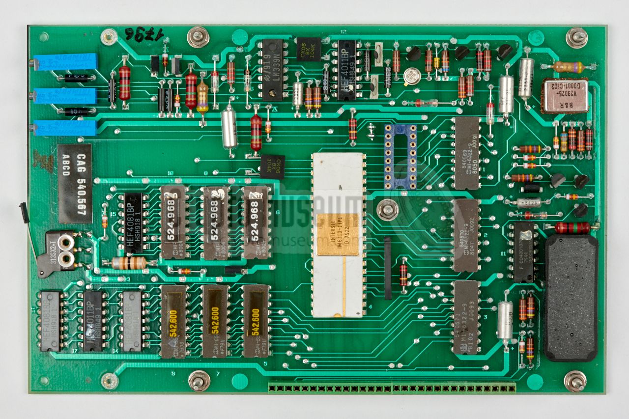
The image above shows the three ROMs in sockets, on an early prototype
of the processor board. The machines that had been delivered to the
Argentines (and others) did not have sockets, and had to be reworked by a skilled engineer.
A few months later, mid-1979, Peter Jenks
left the NSA and
Dave Frasier committed suicide.
It was one of the greatest losses at NSA during the course of
Operation RUBICON.
Jenks
and Frasier
had been the architects of the NSA-developed (rigged)
cryptologics that were used in CAG products. To lose them both was devistating [7].
|
|
|
Around the same time, the Argentine Navy discovered the weakness 1 in
the cipher algorithm as well, and
demanded an immediate explanation.
Crypto AG's CEO, Heinz Wagner, was invited to Buenos Aires, and was
confronted with the attack, which was similar to the one by Jürg Spörndli.
Wagner, being afraid to be thrown off an
airplane, 2 immediately offered the NSA-fix.
He was lucky. They accepted the fix,
but what the Argentines really wanted, was the ability to
attack their neighbouring countries, and the promise that CAG would
not tell them about the vulnerability [7].
The matter was settled more permanently in 1981, after a newly recruted
cryptomathematician — codenamed ATHENA — completely redesigned the
cryptologic 3 so that it seemed
much more robust and could withstand advanced known plaintext attacks.
In reality though, it was just as weak as its precedessor,
allowing NSA and ZfCh to continue to read intercepted messages [7].
➤ More about Operation RUBICON
|
|
-
The CIA suspected that Peter Frutiger – a disaffected former employee –
might have tipped them off, but this was never proven.
-
This refers to the so-called death flights during the
Argentine Dirty War (1974-1983), in which dissidents and enemies
were dropped to their death from aircraft above the ocean.
➤ Wikipedia
-
After the upgrade, the length of the Basic Key (BK) was increased from
10 to 20 letters, but is not reflected in the manual or
the instruction chart. Existing HC-520-003 units were retrofitted
with the new firmware.
|
|
The HC-520 is housed in a shock-resistant
ergonomic enclosure, made of high-quality
durable plastic, which consists of a black bottom part and a cream – in the military
variant: olive green – upper case shell. In order to access the interior of
the device is it necessary to remove the battery
by releasing two large bolts at the bottom
of the device with a large screwdriver or a small coin.
|
|
The three boards
are interconnected by means of two single-in-line headers,
located at the left and right side respectively, with the middle board
acting as the central hub. Each board has a set of metal positioning pins
along its side, that mate with holes in the board to which it is fitted.
|
At the centre of the stack is the
display/interface board, which holds
the keyboard interface and the display circuitry. This multi-layer PCB
has a embedded flex PCB which extends from the far end, ending under
the glass of the LCD display.
The LCD is seated in a grey plastic cradle which is curved at the rear
side, to prevent the flex PCB from breaking. It is
connected to the tracks of the flex PCB
by means of two tight-fitted zebra contact strips, and is held in
place by two metal retaining clips. It is one of the first LCDs, and was
custom-made for Crypto AG
by Siemens.
|
|
|
|
The display/interface board has a conformal coating on both sides, which
makes it more robust, but also more difficult to repair. The smaller
keyboard is fitted to a row of contact pins at the top side of this board,
whilst the board itself it fitted to a green contact header on the lowest board.
|
At the bottom of the stack is the
processor board,
which also holds the power circuitry. At the corner of the board is a
bi-stable relay that
is controlled by the ON/OFF keys on the keypad.
At the center of the board is a 12-bit PDP-8 compatible microprocessor,
with a variable clock frequency between DC and 4 MHz. For the first
production runs (1977), the
Intersil IM-6100 was used, but in later batches
(1981) it was replaced by a
Harris MI-6100 which is pin-compatible.
The firmware is stored in three 4-bit wide Harris MI-6322 masked ROMs
(total width of 12 bits).
|
|
|
|
At the other side of the processor is the Random Access Memory (RAM),
consisting of six Harris MI-6561 256 x 4 bit CMOS RAMs —
organised as two sets of three chips each to get a 12-bit wide bus —
giving a total memory space of 6 Kbit or 768 bytes, of which 590 bytes
are used for storage of the message. The remaining 178 bytes hold
the basic key, the message key and some internal (software) values.
Power to these RAMs runs via the
tamper switch
at the far side of the board. When the
case retaining bolt is loosened,
the contents of the RAM are purged instantly.
|
Below is the simplified block diagram of the HC-520. At the bottom right is
the battery that powers the lot. The power circuit is controlled
by the ON and OFF buttons on the keypad at the bottom left. It delivers power
to the processor board and to the display/interface board, and also generates
the clock for the IM-6100 processor, which can be anything
between DC and 4 MHz.
The RAM chips are powered directly from the battery, but the power line
is routed via a tamper switch of which the contacts are kept closed by the
case retaining bolt.
Removing this bolt, cuts to the power to the RAMs
and deletes the message and the keys instantly.
|
|
Although the HC-520 is a small device with a fairly simple user interface,
its internals are quite complex, making it difficult to repair a broken
device. Nevertheless it is surprising to see that most of the surviving
devices still work well after more than 40 years, with only minor issues.
|
By far the most common problem is damage to the processor board
caused by a leaking backup battery. Although
it was recommended to have it replaced every three to four years,
it is doubtful whether any of the customers have done so, as it required the
device to be returned to Crypto AG.
The backup battery is soldered-in at a corner of the processor board,
as shown in the image on the right. It holds three cells
and is hermetically sealed. Nevertheless, the chemicals from leaking
cells always find a way out – especially after 40+ years – and may
cause damage to the circuitry.
|
|
|
|
As the battery is close the the power-on and wakeup circuit, the damage
may prevent the device from starting up properly.
Depending on the amount of leakage and the time that has passed,
the damage may vary between hardly visible parasitic conductivity, and
corrosion between the legs of the parts
or even completely
destroyed PCB tracks and solder joints that are no longer solderable.
|
In most cases, the damage to the processor PCB is reversable, but
if it has affected the display & interface board (which is fitted just
above it) the chemicals may have penetrated the layers of the board, in
which case it will be beyond repair.
In any case it is important to remove the backup battery as soon as
possible. Although it can be replaced by a modern alternative,
it is better to leave it out altogether to prevent future damage.
The device will work perfectly well without
the backup cells, although the keys and the message will be lost
when the main battery is removed. 1
|
|
|
|
The image above shows the processor board after the backup battery
has been removed. Note that all traces of corrosion must be removed,
especially between the legs of the ICs. Also note that the through-plated
holes (that connect the tracks at both sides) may have been damaged.
|
Another frequent failure is the LCD display, that might have been 'eaten
away', as shown in the image on the right. This is caused by acid gasses
that are emanated from the acetate carrier of the polarising film, in combination
with the glue of the reflective foil at the back. This process might have been accelerated when the device has been exposed to high temperatures or high humidity.
In many cases, the display still works, but it will be difficult to see that.
After some experiments, we found out that it was possible to repair it,
but this requires a steady hand and a lot of patience.
|
|
|
|
First, the four screws that keep the LCD in place are loosened.
The two metal clamps (above and below the LCD) can now be shifted outwards,
so that the glass is freed up. Next, the glass body of the LCD is
removed from the plastic cradle, but this has to done very carefully,
so that the zebra-strips — that provide the contact between the glass and the
flex PCB — are not damaged.
|
When repairing an LCD, it is important to have a good
understanding of its working principle. A detailed description can be found on Wikipedia [5]. It is based on the effect that liquid-crystal changes the polarisation
of incoming light, and that it doesn't do that when a voltage is applied.
The heavily deteriorated reflective foil and the remains of the horizontally
polarising filter were carefully removed, along with their glue residues at
the back side of the glass. As the vertically polarising filter at the front was
also in very bad condition, it was decided to replace that as well.
|
|
|
|
After replacing the two polarising films, and adding a new semi-reflective foil at
the back, the contacts inside the cradle were cleaned and the complete glass
package was reseated in the cradle. Next, the two metal clamps were shifted back in
place and the four screws were tightened.
|
The result is shown in the image above. The LCD display now produces a crisp and
clear image again, just like it did when it was brand new.
Another area that requires attention is the keyboard. Although it does not
contain any active parts, it may not be repsonding properly, as a result of
dirt under its contacts. Repairing it is straightforward,
but requires some patience.
First, the rubber key-mat has to be removed, after which the
tactile switches become visible.
They are embedded in a layer of PCB material.
|
|
|
|
Next, the cellotape that keeps the spring-contacts in place,
has to be removed, along with all of its residues. The spring contacts can now
be removed and can be cleaned separately, leaving the PCB to expose its
inner layer with silver-plated contacts,
as shown in the image above.
After cleaning the sliver-plated PCB contacts (with a suitable solvent),
the spring-contacts can be reseated, after which a couple of narrow cellotape strips
should be used to keep them in place.
|
-
Unless an external power supply is connected when the battery
pack is removed.
|
The display of the HC-520 is a FAS11101R, which was custom-made
by Siemens in Germany.
Its construction is shown in the diagram below.
The actual LCD is the glass package at the centre. It consists
of the liquid-crystal molecules, which are sealed between two
etched glass panels. If the sealing breaks, the display is lost,
so the glass package should remain a one-piece construction.
The shapes of the segments are etched as electrodes in the upper glass,
whilst the lower glass acts as the common electrode.
By default (when no voltage is applied) the liquid-crystal rotates
the polarity of the incoming light by 90°.
When a voltage is applied to the electrodes, the liquid crystal looses
this property and lets the
light straight through (without rotating its polarity).
By placing a vertically polarising filter in front of the glass package
and a horizontally polarising one behind the glass, the light gets blocked
locally, whenever a voltage is applied to one or more segments of the
liquid-crystal. At the bottom of the stack
is a semi-reflecting sheet that reflects the incoming light. It raises the
contrast and gives the display its neutral background.
|
Over the years, Crypto museum has seen (and repaired) several HC-520
units. Although most units worked well many years after they were
decommissioned, there were some that would start properly one moment,
and completely freeze when started again (showing all display segements).
This problem is caused by the fact that the HC-520 does not have a proper reset
circuit for the IM-6100 microprocessor, probably in combination with ageing
of some parts. In that case, it is recommended to add a simple reset
circuit to the processor board, by soldering a 100K resistor and a
1µF capacitor directly to the legs of the IM-6100,
as shown in the diagram above.
|
|
Apart from the batteries, the HC-520 can also be powered externally,
by supplying 6 to 7.5V DC to the recessed DB9 socket at the rear. This
can also be used to charge the batteries. Although it
has 9 pins, only two of them are used. Below is the pinout
when looking into the socket.
|
- (+) 6V DC
- n.c.
- n.c.
- n.c.
- (-) 0V
- n.c.
- n.c.
- n.c.
- n.c.
|
|
Alphabet Latin (teleprinter) with 52 characters Memory 590 characters Power 6 - 7.5 V DC (automatic shut-off when over 8V) Current 10 mA Dissipation 60mW (battery) Battery 5 × 1.2V/0.5Ah NiCd cells (or 5 × 1.5V AA-size dry cells) Duration 50 hours (200 hours with dry cells) Charge 15 hours Dimensions 245 × 129 × 44 mm Weight 976 grams (without batteries) Temperature 0° — +50°C (storage: -30° — +70°C)
|
Basic 10 letters → 2610 = 1.4 · 1014 ≈ 247 Message 10 letters → 2610 = 1.4 · 1014 ≈ 247 Period (25 - 1)5 · (231 - 1)5 = 1.3 · 1054 ≈ 2180
|
Basic 20 letters → 2620 = 1.99 · 1028 ≈ 294 Message 10 letters → 2610 = 1.4 · 1014 ≈ 247 Period (25 - 1)5 · (231 - 1)5 = 1.3 · 1054 ≈ 2180
|
-
Around 1978, the cryptographic algorithm of the HC-520 was improved
and the length of the BASIC key was increased from 10 to 20 characters.
This is not reflected in the manual and the instruction card.
|
It is currently unknown how many HC-520 units were manufactured,
but according to one source, about 700 units were made [2].
This is likely to be correct.
The HC-520-001 prototype in our collection has
serial number 043, which
could indicate that around 50 prototype units were built.
From another source we obtained a list of serial numbers
that were observed in Argentina [3]. Based on the manufacturing
codes and serial numbers on these devices, its seems likely that
they were sold in two batches: 50 units in 1977
and at least 150 units in 1981 1 .
The units that were delivered to Argentina, all carry the designator
HC-520-003. Furthermore, the first batch carries the manufacturing
code ST 540 614A, whilst the second batch is marked ST 540 688A.
|
-
Estimated from observed date codes on the components.
|
-
Around 1981, the cryptographic algorithm of the HC-520 was improved
and the length of the BASIC key was increased from 10 to 20 characters.
This is not reflected in the manual and the instruction card.
-
Anstalt Europaische Handelsgesellschaft (AEH) was the official owner of
Crypto AG
and its intellectual property, established in tax paradise
Lichtenstein to hide the true ownership of the company.
➤ More
|
|
|
|
Any links shown in red are currently unavailable.
If you like the information on this website, why not make a donation?
© Crypto Museum. Created: Monday 10 August 2009. Last changed: Wednesday, 05 November 2025 - 11:49 CET.
|
|

|
|
|


![Original HC-520 PSU (PSM-107-001). Photograph kindly provided by Klaus Kopacz [6].](img/hc520_charger.jpg)


![Bottom side of the original PSU. Photograph kindly provided by Klaus Kopacz [6].](img/hc520_charger1_thumb.jpg "image # hc520_charger1.jpg")


![Bottom side of the original PSU. Photograph kindly provided by Klaus Kopacz [6].](img/hc520_charger1.jpg)


