|
|
|
|
|

|
|
Hagelin Pin-wheel C-443 → ← BC-38 ← M-209
Motor-driven pin-wheel cipher machine with keyboard
The BC-543 is a rather strange member of the Hagelin family. As the name
suggests, it was developed around 1943. It is not based on the earlier
C-52 however, but on the nearly identical
BC-38 which in turn was based on the
C-38,
a.k.a. the war-time M-209.
The BC-543 is in fact functionally identical to the
BC-38
and M-209
and differs only in minor manufacturing details.
|
One of the most obvious differences with the BC-38 is the absence of the
large slide resistor just behind the cipher wheels that was used to adjust
the mains voltage between 110 and 220 Volt. On the BC-543,
it is hard-wired and can be changed with an
internal voltage selector plug.
The image on the right shows a typical BC-543 unit
that was used between in the 1950s and 60s by the Dutch Army [1],
where it was known as the MX-3002
[2].
Although the machine has seen many years of service,
it is still in excellent condition.
It is shown here without the top cover.
|
|
|
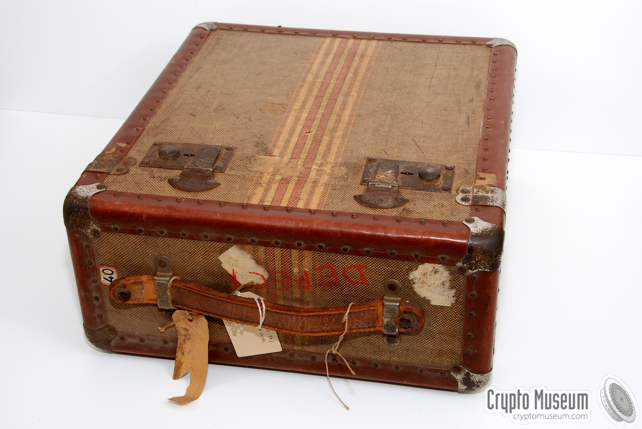
When not in use, the BC-543 was commonly stored inside a
protective case,
that has soft padding on the inside, in order to protect the machine during
transport. The lid of this case has a
hidden compartment with the
mains power cable and – in some cases – some spare parts or supplies.
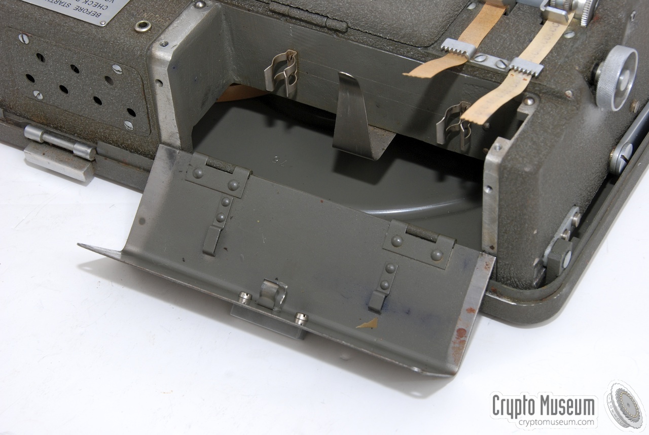
At the rear is a small compartment with a hinged lid,
behind which the common maintenance accessories are stored, such as the oil tube,
the ink tube, a pair of tweezers and a plastic box with spare parts.
On the earlier BC-38, this space was used for the mains voltage slide resistor.
Unfortunately, the maintenance tools and spares are missing from the machine
shown here.
|
|
Each machine comes with two different keys: one for the operator that can only
be used to remove the dust cover, and one for the crypto-officer, that allows
the daily key to be set. The operator's key has a single cut-out in the circumfere,
whilst the officer's key has two of these.
The message key could be set by the operator by altering the initial position
of the coding wheels. For this, the operator didn't need to have access to the
machine's interior.
Opening the top lid of the machine with the special officer's key,
reveals the interior.
|
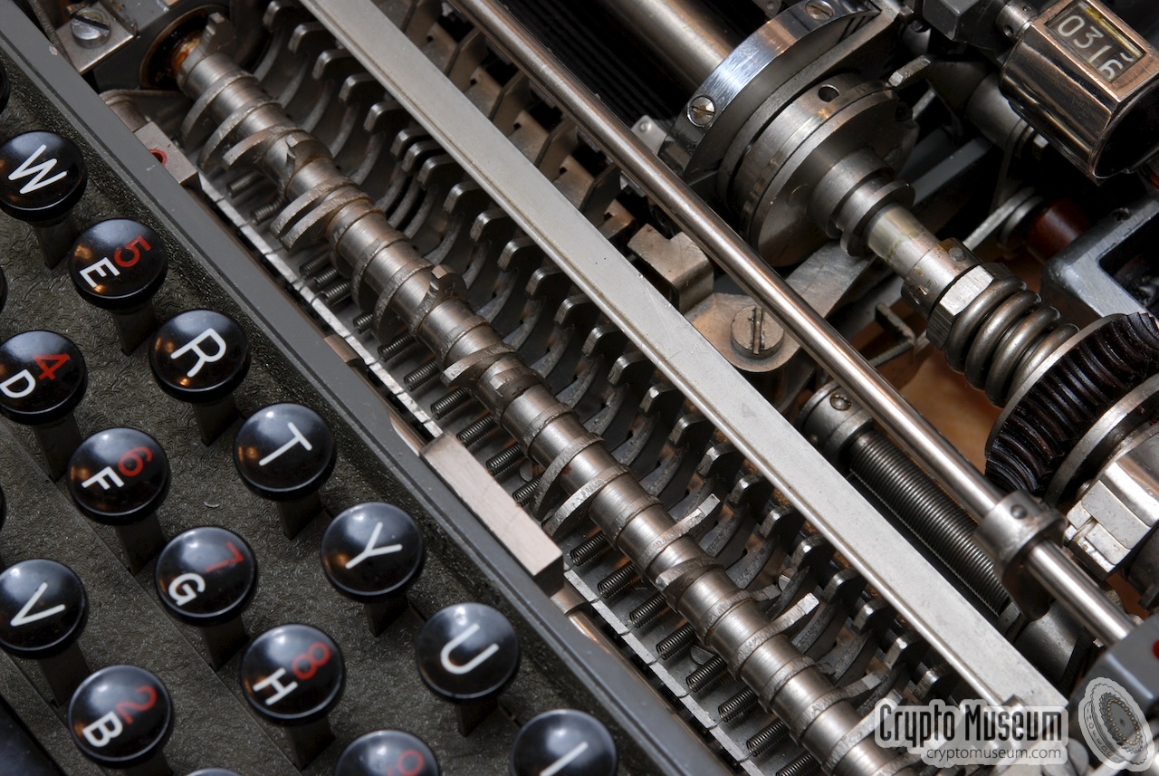
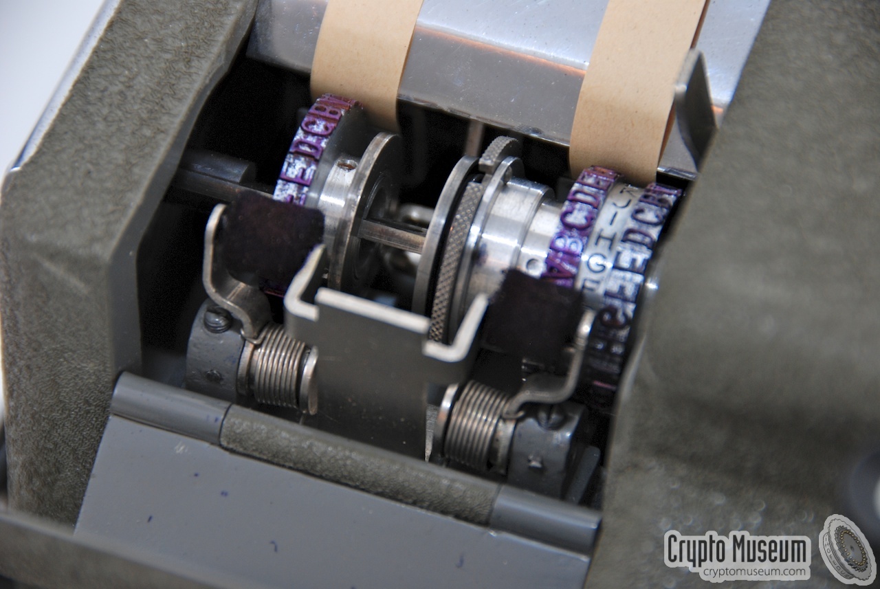
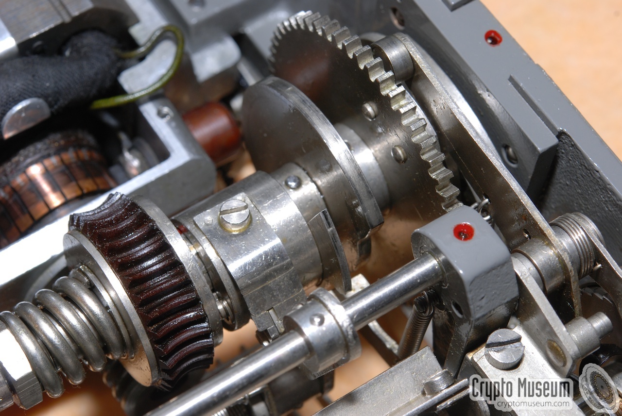
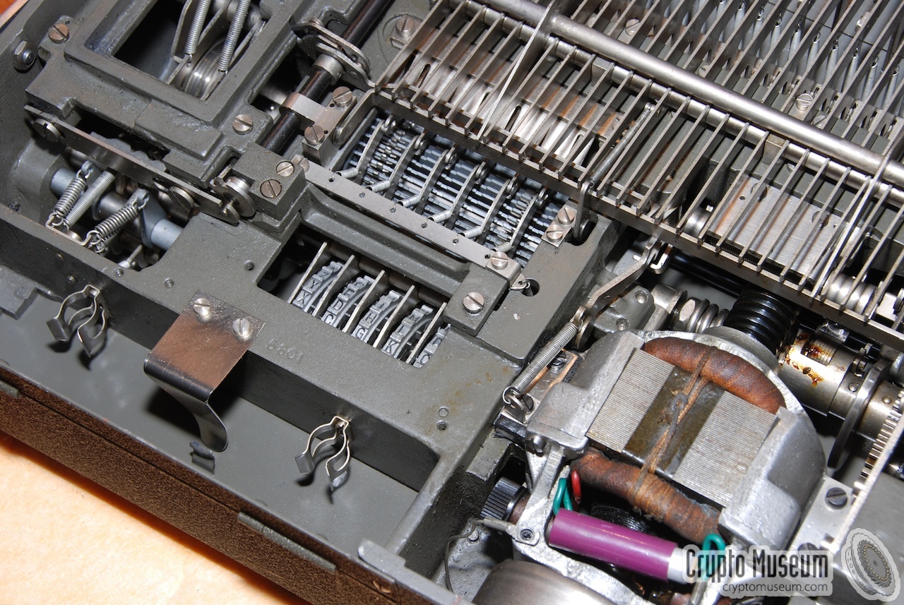
At the heart of the machine are the usual coding wheels and
the rotating 'cage', very similar to those of, say,
the M-209.
The only difference is that in the BC-543 they are mounted upside-down (see the
image on the right).
The main difference with a smaller Hagelin machines, is the presence of a
keyboard. Behind the keyboard is a large axle with notches,
which effectively 'translates' a key from the keyboard into a rotation (angle)
of the axle, much like setting the alphabet wheel on the left side of the
smaller machine (image 3 and 4 below).
|
|
|
The machine can be operated in two ways: with the build-in motor, or with the
retractable handle. The latter can be useful in areas with no mains power,
or in case of a power failure.
When the built-in motor of the BC-543 is used, the whole coding/decoding
process is fully automated and the operator can encipher a message at
typing speed.
|
As the keyboard was considered a useful addition to a mechanical
cipher machine, Hagelin developed a range of external keyboards for
their existing range of smaller machines.
One example is the B-621 keyboard
that was used with the CX-52.
|
|
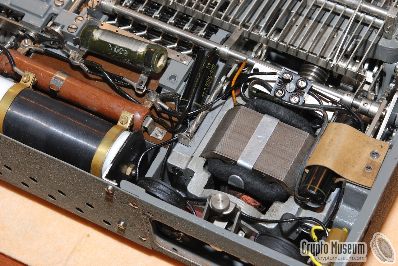
The BC-38 is a very complex mechanical machine. Although it is driven
by an electric motor (see below), the entire
enciphering/deciphering is mechanical.
Basic operation of the machine is identical its non-electric
equivalent, the C-38
and the M-209.
On the M-209, the user has to enter a letter by setting a letter wheel
at the left side of the machine and then engaging the mechanism manually,
whereas the BC-38 allows a letter to be typed directly on a keyboard,
whilst the mechanism is moved by an electric motor.
|
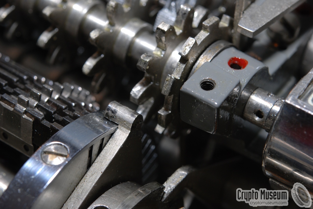
Each letter of the keyboard is converted into a rotation (angle) by
means of a large notched axle that is mounted just behind the keyboard.
It is clearly visible in the image on the right (top left to bottom right).
Each notch is mounted at a different angle that corresponds to the
angle of the same letter on an M-209.
When the machine is turned on, the motor starts spinning at a
constant speed, whilst the rest of the mechanism is in rest.
Pressing a key on the keyboard initiates a series of actions,
which are described in detail below.
|
|
|
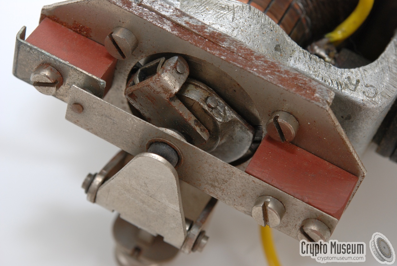
First of all, when a key is pressed, the rest of the keyboard is blocked,
whilst the notched axle, or alphabet shaft, moves to the desired angle.
This involves the activation of two mechanisms.
One mechanism, located at the left
(image #2), releases the wound-up alphabet shaft,
whilst the second one blocks the keyboard. The latter is located
behind the alphabet shaft, close to the main spindle.
It is the part with the large spring, clearly visible in
image #3.
When this has happened, the mechanism is coupled to the main
motor-driven spindle at the heart of the machine.
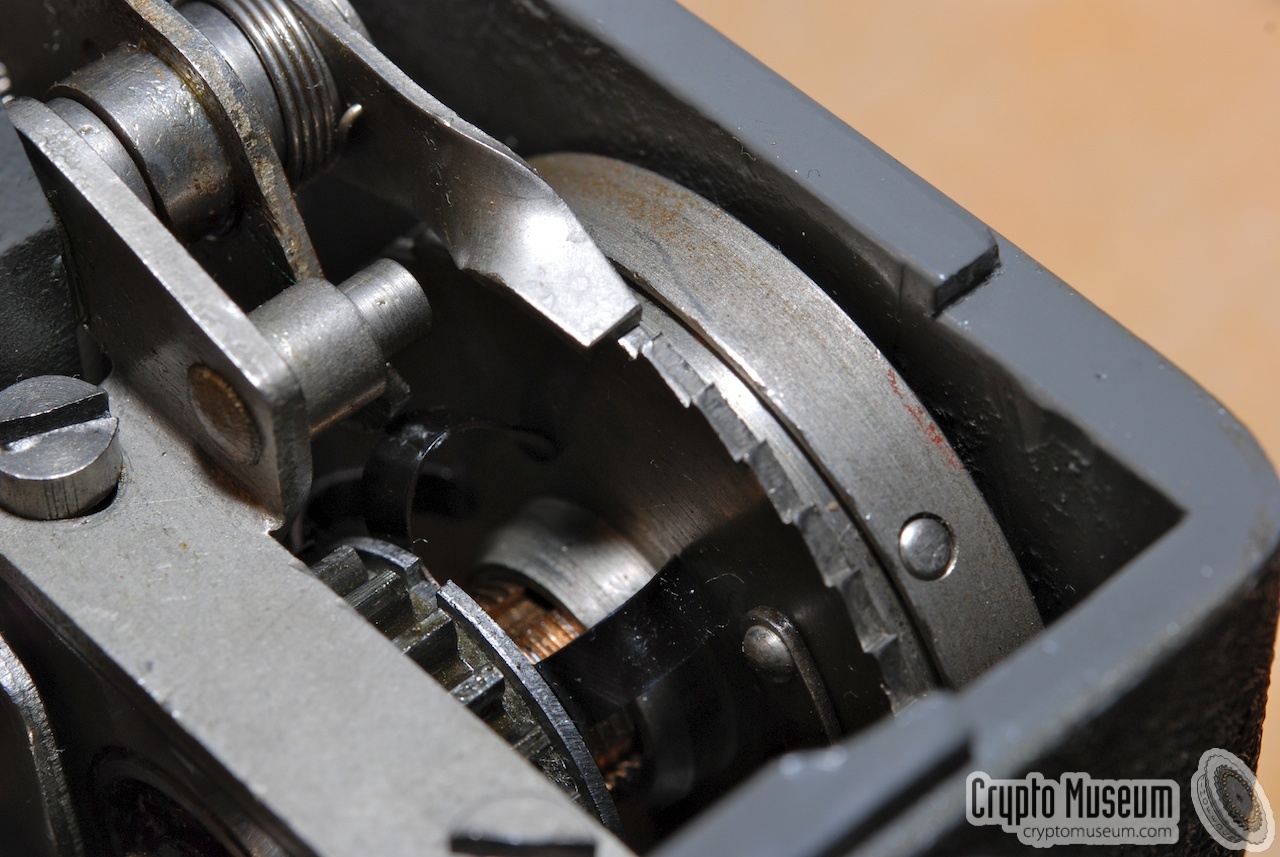
As a result, the cage makes a full revolution.
At the end of this revolution, the result is printed onto a
paper-tape (#4
and #5).
At the same time, the cipher wheels are moved to
the next position, by a rounded notch on the circumfere of
the cage (#6).
When the cage makes its revolution, the drive gear at the right
hand side (#7) is rotated as well.
It winds-up a small spring-loaded mechanism to the right of the
alphabet shaft (#8), so that the
shaft is ready to encode the next letter.
The gear mechanism at the right is also used by the
retractable handle at the right of the machine.
|
Different versions of the BC-543 exist.
The electric circuit of the initial BC-543 is very simple.
It is nearly identical to that of the earlier BC-38.
Electric current is only used to power the motor and not
for the encryption process.
Only a few additional components are used to connect the motor directly
to the mains, as shown in the circuit diagram below.
A large wire-wound adjustable resistor in the power rail,
allows the machine to be used on both 110V and 220V.
Note that this resistor runs very hot when powering the machine from 220V,
as it dissipates half the energy.
The BC-543 is driven by a so-called universal motor
[1]
.
This is basically a 110V series-wound motor designed to be powered
from both DC and AC sources. Such motors have a high torque on
startup, but have the nasty side-effect that the speed (RPM)
keeps increasing when it has no load.
An adjustable wire-wound resistor (Ra), connected in series with the motor,
allows the machine to be powered from a 220V mains network.
A capacitor (C2) is connected directly to the brushes of the armature
of the motor, in order to reduce sparks caused by the commutator.
|
|
In the initial version of the BC-543, motor speed is controlled by a so-called
centrifugal switch (S2).
On startup, the motor is connected directly to the mains.
Once it has reached its nominal speed, the centrifugal switch
is opened, which effectively turns off the motor.
As a result, the rotational speed will decrease and the contact will
close, after which speed increases again, etc.
|
Two coils (L1 and L2) and a capacitor (C1) are used to protect the contacts
of the switch (S2) and reduce sparks. A varistor (Rv), connected in parallel
to the switch, is used to further reduce the extremely high voltages
caused when opening and closing the contacts of S2.
Furthermore, two resistors (R1 and R2) are connected in parallel to the
speed control circuit, in order to prevent the current from dropping to
zero when opening the contacts of S2. They effectively reduce the
quality factor (Q) of the resonance circuit (L1, L2, C1).
|
|
|
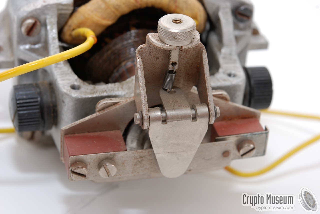
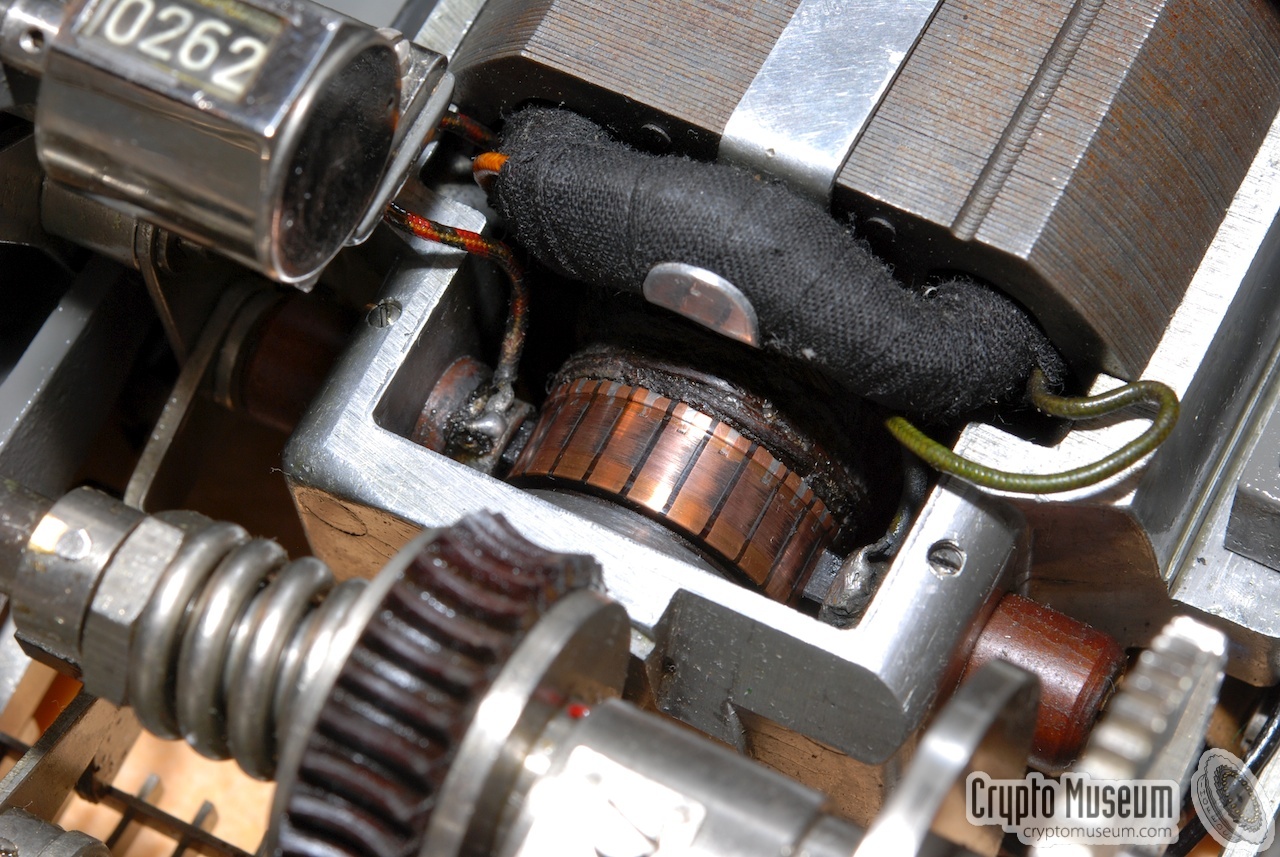
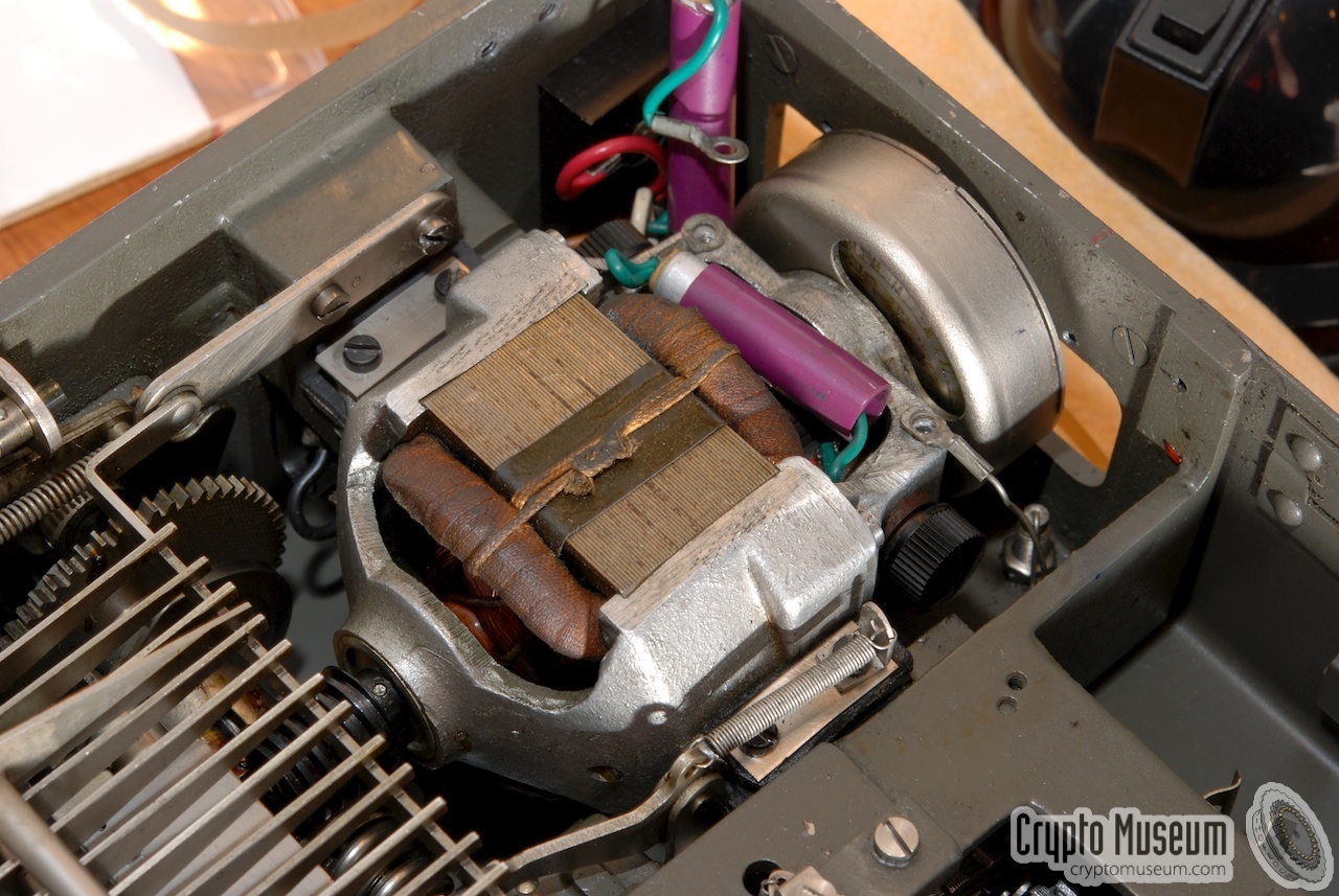
The image above shows the motor of a Hagelin BC-543.
Compared to the motor of the BC-38,
the armature is mounted the other way around.
The commutator is clearly visible at the centre.
The construction at the front is the centrifugal switch.
It can be adjusted with the knurled knob.
|
|
As most BC-543 machines are over 60 years old now, you may encounter
problems with a leaking capacitor (C1).
If this capacitor runs hot after the machine has been on for a few
minutes, it is likely to start leaking shortly.
If this happens, the centrifugal switch (S2) is shorted and can no
longer control the motor's speed, resulting in a so-called runaway.
If you suddenly hear the motor speed gradually increasing, this is
exactly what is happening.
In such cases you should turn the machine off immediately
and replace C1 by a modern alternative (100 nF, ≥ 500V).
|
At some point, the design of the BC-543 was improved and simplified.
Around serial number 5500, the motor was replaced by a version with
6 rather than 2 connections. Both field windings of the motor (f1 and f2)
were split into two sections, so that they could be connected either in
parallel or in series, depending on the selected mains voltage.
The circuit diagram below shows the simplified circuit diagram of
the improved machine.
Because of the additional field windings, the motor could be wired for
either 110V or 220V. As a result, the large wire-wound slide potentiometer
fitted at the back of the machine was no longer needed. The space that
was previously taken up by the potentiometer, was now used for a compartment
where the ink and oil tubes, and the maintenance kit were stored.
At the same time, the centrifugal switch was replaced by a
centrifugal brake, which means that the additional components from the
original diagram (S2, L1, L2, Rv, C1, R1 and R2) could be dropped as well.
Selection of the correct mains voltage, was done by adding an ingenious
pin-operated selection switch, which is shown in the drawing below:
Three pins are mounted on a horizontal plastic bar. These three pins
have no connection between them (i.e. they are isolated), but are used
for shorting two contacts at either side of each pin.
In the above drawings, the voltage selector is shown in the 220V position.
|
When restoring a BC-543 of the first type, it is advised to
replace all capacitors and modify the circuit slightly, as shown in the
diagram below. This prevents the full mains voltage to be connected to
the chassis when the main plug is inserted the wrong way around and the
power switch is OFF. For safety reasons, you should always use a mains
cable with an earth wire and connect it to a wall socket that has a
ground terminal.
|
-
Document kindly provided by
Historische Collectie Verbindingsdienst
via BartW. November 2017.
-
This document describes the Hagelin M-209 and the C-446A in great
detail. Not only is the working principle of the machines explained,
it also discusses the machine's cryptanalysis and methods for its attack.
The document is in Dutch and was released for publication in 2011. 2
-
Released for publication in 2011 by DIVI (Dutch School for Military
Intelligence) [1].
|
- Dutch Department of Defense, Defensie Inlichtingen en Veiligheids Instituut (DIVI)
BC-543 courtesy of DIVI, donated in 2010.
- Museum Verbindingsdienst, Dutch Royal Signals Museum
Visiten 2010.
- SMID, C-446A en M-209 Beschrijving en Analyse
Descryption and analysis of the Hagelin C-446A and M-209 (Dutch).
Dutch Department of Defence, Military Intelligence School [1].
|
|
|
|
Any links shown in red are currently unavailable.
If you like the information on this website, why not make a donation?
© Crypto Museum. Created: Thursday 01 March 2012. Last changed: Sunday, 14 April 2024 - 11:26 CET.
|
 |

|
|
|


![Hagelin BC-543, kindly donated by DIVI [1]](img/300813/015/full.jpg)