|
|
|
|
|

|
|
Hagelin USA Pin-wheel BC-543 → M-209 → ← C-37
Pin-wheel cipher machine with keyboard and motor
BC-38 was an electromechanical
cipher machine developed around 1939 by
Boris Hagelin,
and built by A.B. Cryptoteknik in Sweden (later: Hagelin).
As the name suggests, it was derived from its mechanical equivalent: the
C-38.
The model number was prefixed by a 'B',
to indicate that the device has a keyboard.
This means that the BC-38 is in fact a C-38
with a motor and a keyboard.
|
The machine measures approx. 34 x 32 x 12 cm and is therefore significantly
larger that its manually operated counterparts.
It also needs an external power source.
The advantage of having a keyboard and motor-driven operation however,
is that it greatly speeds up communication,
e.g. in large command centres.
Furthermore, the BC-38 is equipped with a
double printer at the left;
one for the plain text and one for the cipher text.
The output is printed directly onto a narrow paper tape,
and both printers can be used simultaneously.
|
|
|
Although the machine is intended for operation from the mains power
network (110 or 220V), it can still be operated manually, which is
very useful in case of a power loss.
For this, a retractable handle is present on the right.
It is usually folded down and locked in a neutral storage position,
but can be released easily when necessary.
The BC-38 was popular with the the US Army during WWII, where it was used
to communicate with M-209 machines in the field.
It was also used by the governments of other countries during and after
WWII, such as Sweden and Norway.
Production of the BC-38 started in the late 1030s and continued throughout
the 1940s, until it was replaced with the slightly modified and improved
BC-543. The latter is nearly identical to the BC-38
and is backward compatible.
|
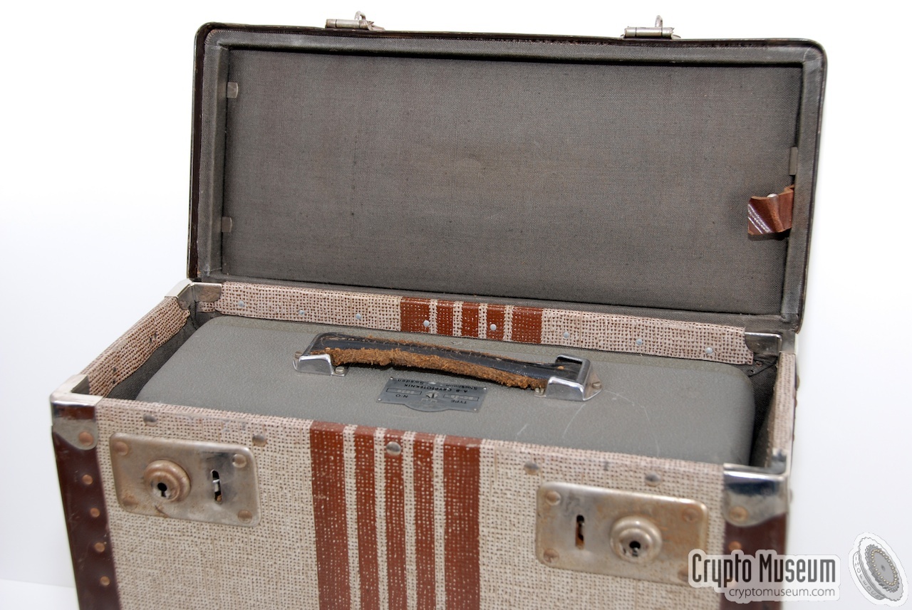
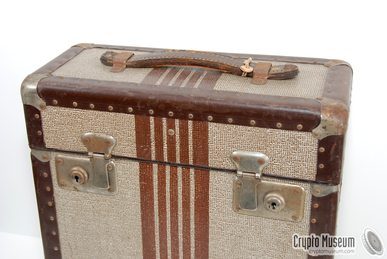
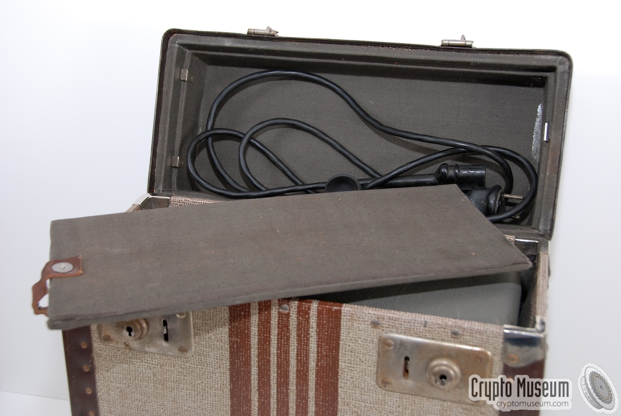
The BC-38 comes with a metal cover that can be placed over the entire
machine, so that it is protected from dust and damage.
The machine can be further protected by using an (optional) storage
case, such as the one shown in the images below. It has soft padding
on the inside.
In most case, the storage case has a padded compartment in the top lid,
inside which the power cable, the maintenance tools and the spare parts
are kept.
|
|
|
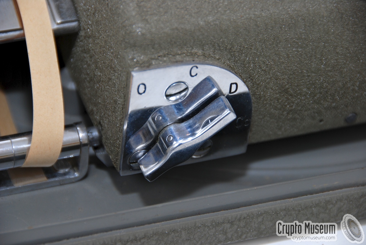
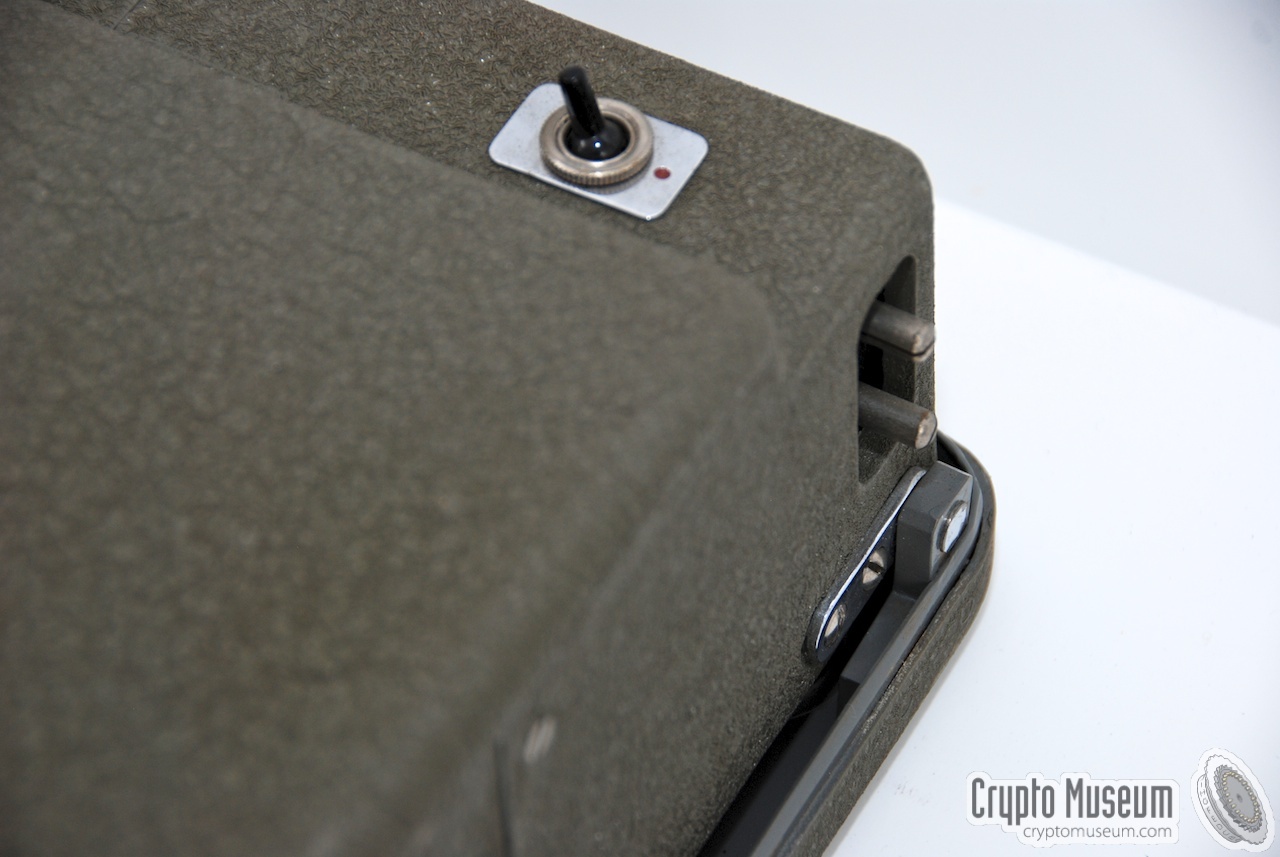
The mains socket is located at the right rear corner of the machine
and consists of 2 pins. The power cable - usually made of rubber -
was stored in a hidden compartment inside the top lid of the storage case.
If this cable is missing, you may have a hard time finding a suitable
replacement.
The correct voltage has to be adjusted with a wire-wound slide resistor,
mounted at the left rear of the machine.
A black knob on top of the machine can be shifted from left (110V)
to right (220V).
|
|
|
|
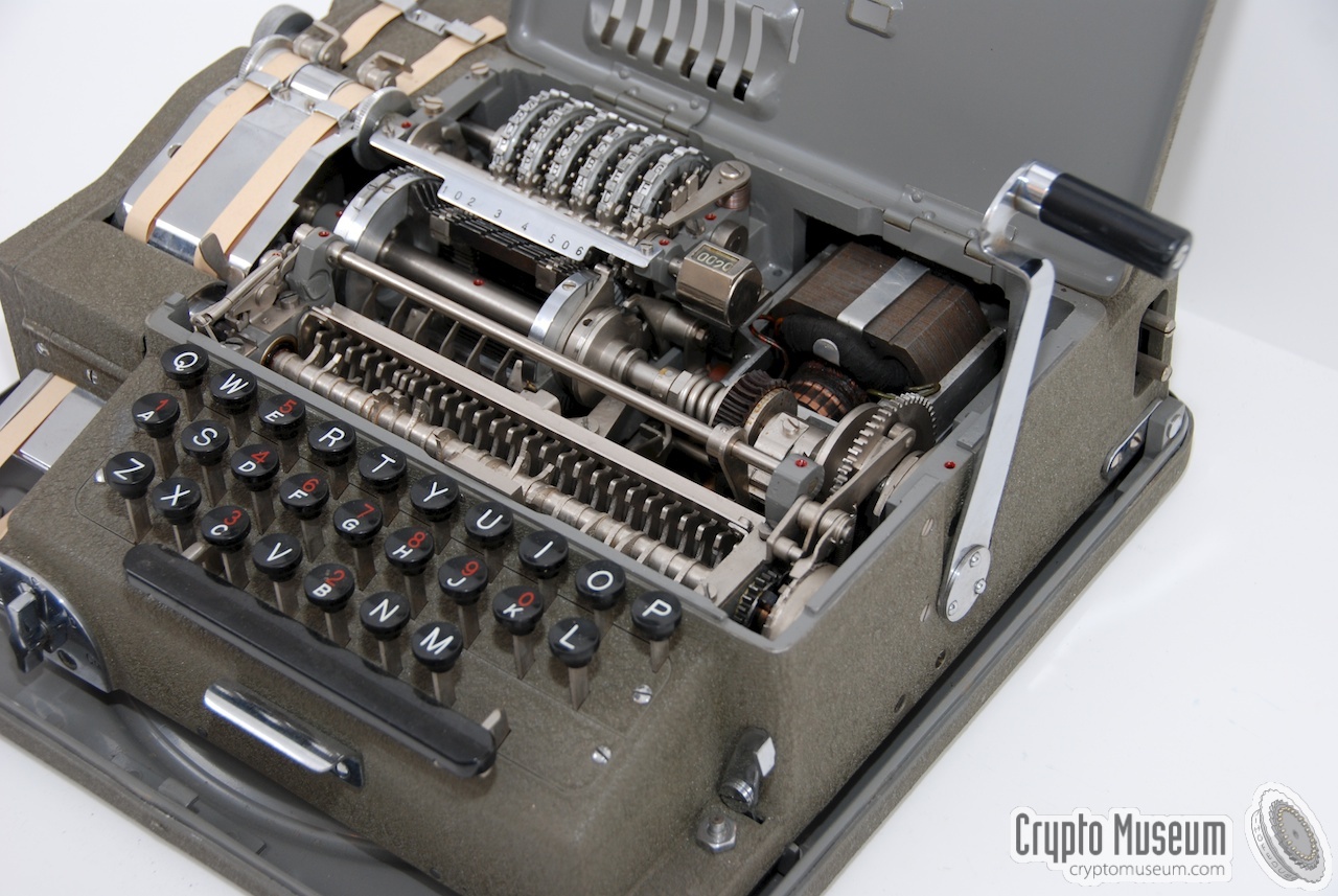
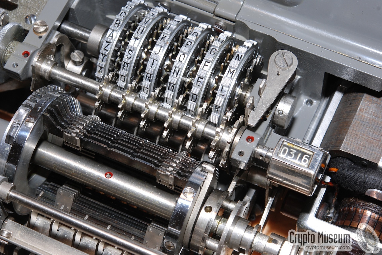
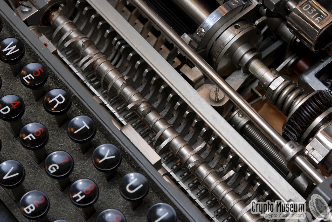
At the heart of the machine is an assembly of cipher (pin) wheels
and a 'cage' with bars and lugs, very similar to the interior of
an M-209. The only difference with the latter is that it is mounted
the other way around, as shown in the close-up image below.
|
The six pin-wheel cipher discs are located towards the back of the machine,
with the wheels protruding the top lid through a series of slots.
A small locking lever to the right of the wheels can be used to
disengage the wheels in order to (re)set them.
Each wheel has a different number of letters on its circumfere.
In front of the wheels is an axle with a series of differently spaced
cogwheels that is used to move the individual wheels during
encipherment. The character counter on the right is connected
to this axle as well.
|
|
|
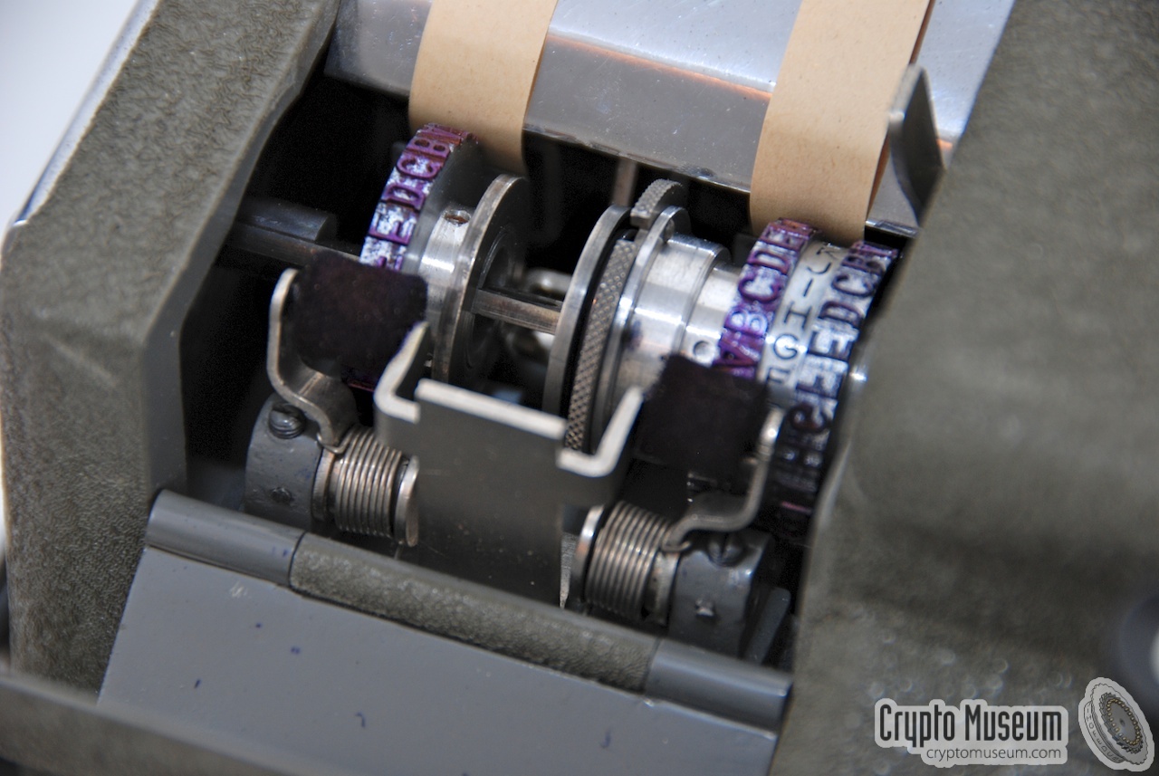
The cage, with the bars and movable lugs, is mounted in front of the
cipher wheels, on the main motor-driven shaft.
To the right of the cage is a coupling mechanism that allows the
machine to be operated without rotating the cage in plain text mode
(shown in uncoupled state here).
|
|
The BC-38 is a very complex mechanical machine. Although it is driven
by an electric motor (see below), the entire
enciphering/deciphering is mechanical.
Basic operation of the machine is identical to its non-electric
equivalent, the C-38
and the M-209.
On the M-209, the user has to enter a letter by setting a letter wheel
at the left side of the machine and then engaging the mechanism manually,
whereas the BC-38 allows a letter to be typed directly on a keyboard,
whilst the mechanism is moved by an electric motor.
|
Each letter of the keyboard is converted into a rotation (angle) by
means of a large notched axle that is mounted just behind the keyboard.
It is clearly visible in the image on the right (top left to bottom right).
Each notch is mounted at a different angle that corresponds to the
angle of the same letter on an M-209.
When the machine is turned on, the motor starts spinning at a
constant speed, whilst the rest of the mechanism is in rest.
Pressing a key on the keyboard initiates a series of actions,
which are described in detail below.
|
|
|
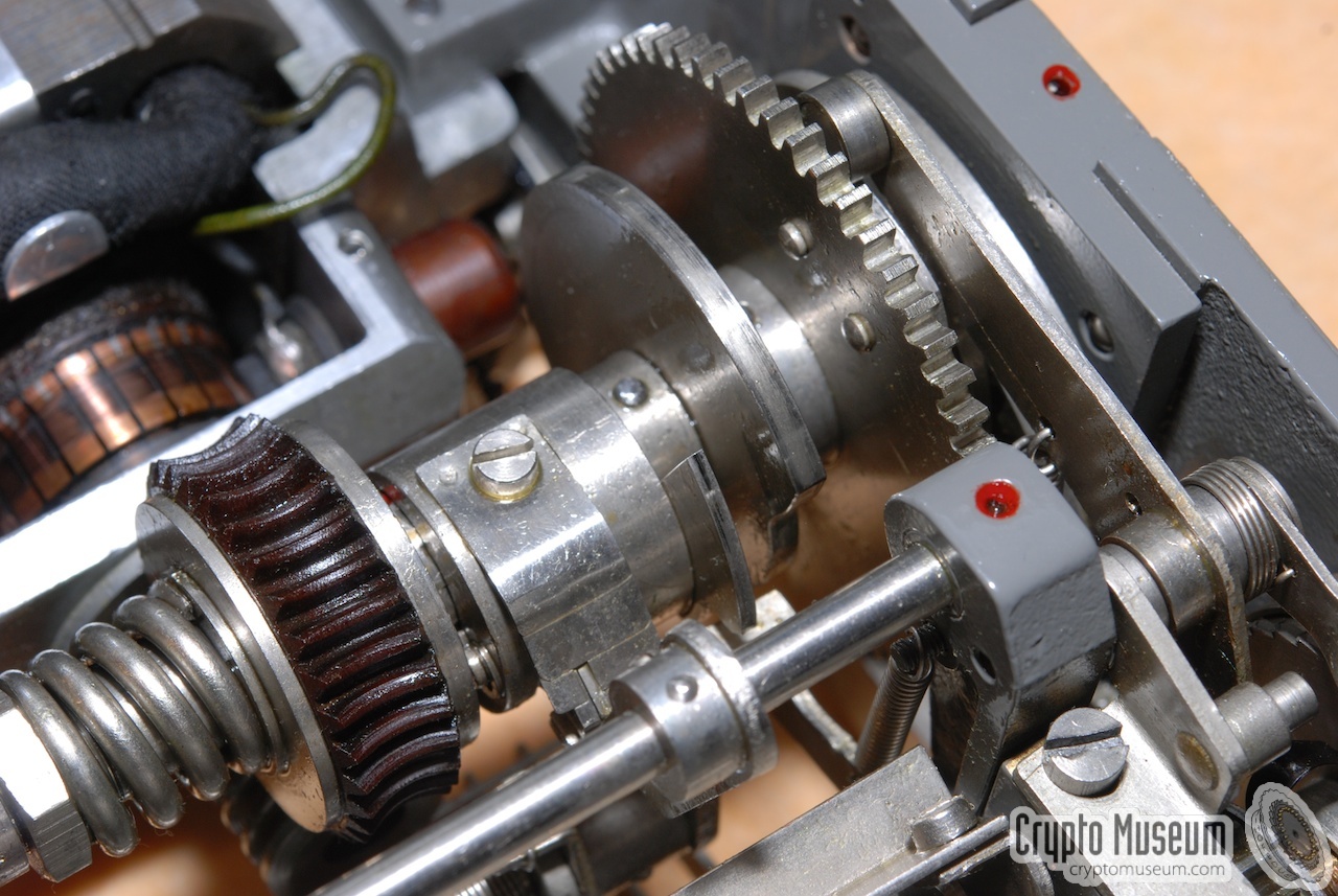
First of all, when a key is pressed, the rest of the keyboard is blocked,
whilst the notched axle, or alphabet shaft, moves to the desired angle.
This involves the activation of two mechanisms.
One mechanism, located at the left
(image #2), releases the wound-up alphabet shaft,
whilst the second one blocks the keyboard. The latter is located
behind the alphabet shaft, close to the main spindle.
It is the part with the large spring, clearly visible in
image #3.
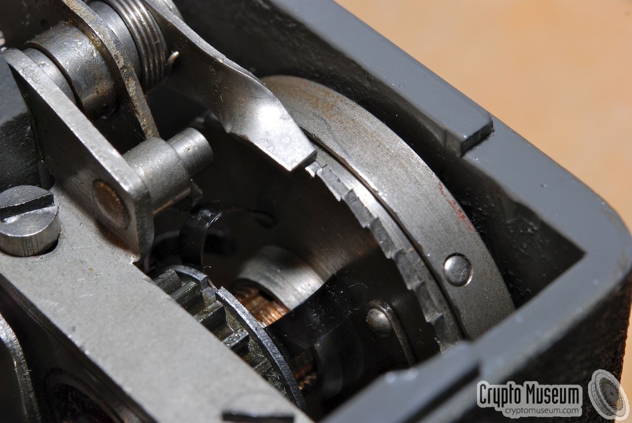
When this has happened, the mechanism is coupled to the main
motor-driven spindle at the heart of the machine.
As a result, the cage makes a full revolution.
At the end of this revolution, the result is printed onto a
paper-tape (#4
and #5).
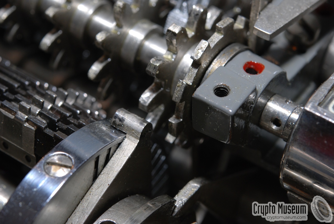
At the same time, the cipher wheels are moved to
the next position, by a rounded notch on the circumfere of
the cage (#6).
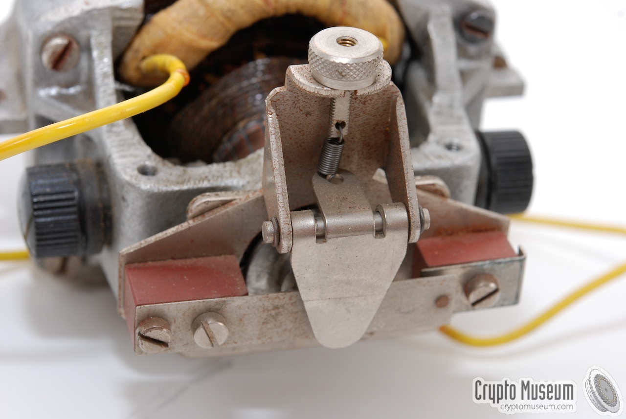
When the cage makes its revolution, the drive gear at the right
hand side (#7) is rotated as well.
It winds-up a small spring-loaded mechanism to the right of the
alphabet shaft (#8), so that the
shaft is ready to encode the next letter.
The gear mechanism at the right is also used by the
retractable handle at the right of the machine.
|
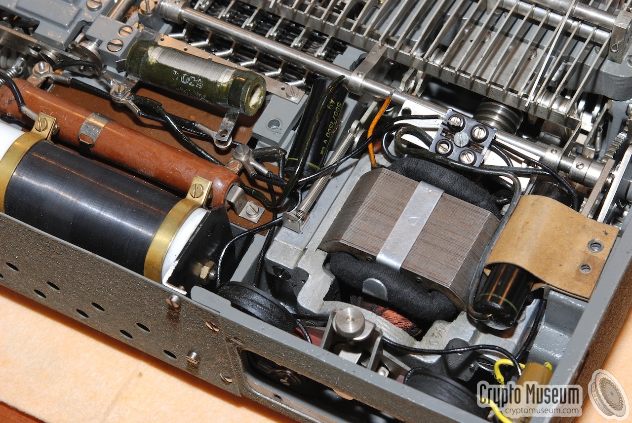
The electric circuit of the BC-38 is straightforward. Electricity is
only used to power the motor and not for the encryption process itself.
A few extra parts are used to connect the motor directly
to the mains, as shown in the circuit diagram below.
A large adjustable wire-wound resistor in the power rail —
accessible from the outside —
allows the machine to be used on 110V to 220V.
The BC-38 is driven by a so-called universal motor.
This is basically a 110V series-wound motor designed to be powered
from both DC and AC sources [1]. Such motors have a high torque on
startup, but have the nasty side-effect that the speed (RPM)
keeps increasing when it has no load.
An adjustable wire-wound resistor (Ra), connected in series with the motor,
allows the machine to be powered from the 110 - 220V AC mains network.
A capacitor (C2) is connected directly to the brushes of the armature
of the motor, to reduce sparks caused by the motor's commutator.
|
|
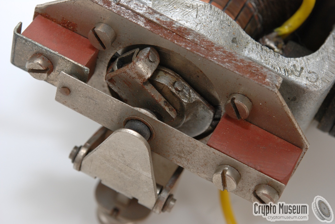
Motor speed is controlled by a so-called centrifugal switch (S2).
On startup, the switch is closed and the motor is connected directly
to the mains (via Ra).
Once it has reached the nominal speed, the switch is opened,
which effectively turns the motor off.
As a result, the rotational speed will be decreased and the contact will
close again, after which the speed increases again. And so on.
|
Two extra coils (L1 and L2) and a capacitor (C1)
are used to protect the contacts
of switch (S2) and reduce sparks. A varistor (Rv), connected in parallel
to the switch, is used to further reduce the counter-electromotive force
(CEMF) caused when opening and closing the contacts of S2 [3].
Furthermore, a resistor (composed of R1 and R2) is connected in parallel
to the centrifugal switch assembly,
in order to prevent the current from dropping
to zero when opening the contacts of S2. They effectively reduce the
quality factor (Q) of the resonant circuit formed by L1, L2 and C1.
|
|
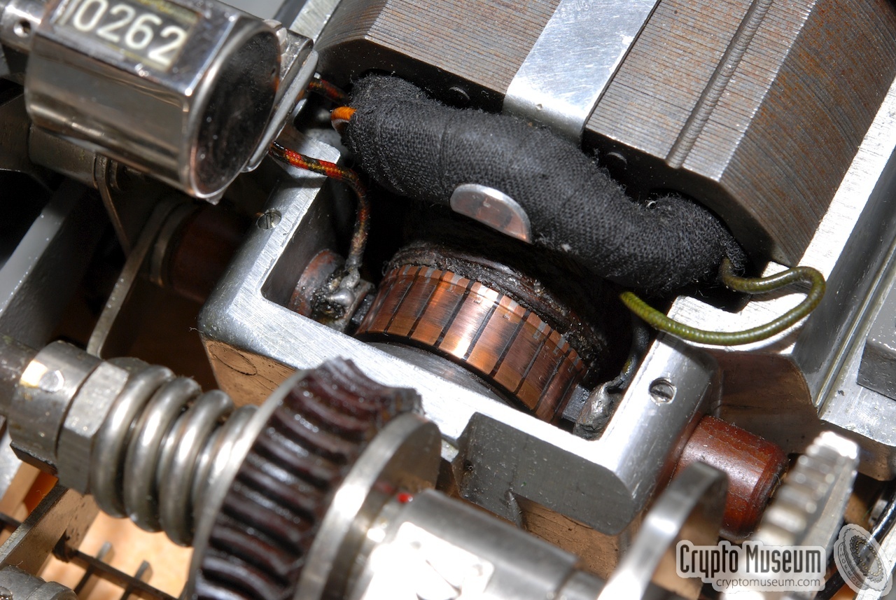
|
The image above shows the motor of a Hagelin BC-543
which is nearly identical to the one used in the BC-38.
The only difference is that the armature is mounted the other way around.
The commutator is clearly visible at the centre and the armature winding
is connected in series with the field windings.
The construction at the front is the centrifugal switch.
Further images below.
|
|
As most BC-38 machines are over 70 years old now, you may encounter
problems with a leaking capacitor (C1).
If this capacitor runs hot after the machine has been on for a couple of
minutes, it is likely to start leaking in the nearby future.
If this happens, the centrifugal switch (S2) is shorted and can no
longer control the motor's speed, resulting in a so-called runaway.
If you notice that the motor speed is gradually increasing, this is
probably what is happening.
In such cases you should turn off the machine immediately
and replace C1 by a modern (high voltage) alternative.
|
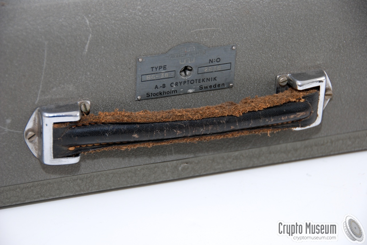
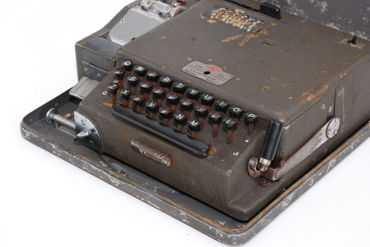
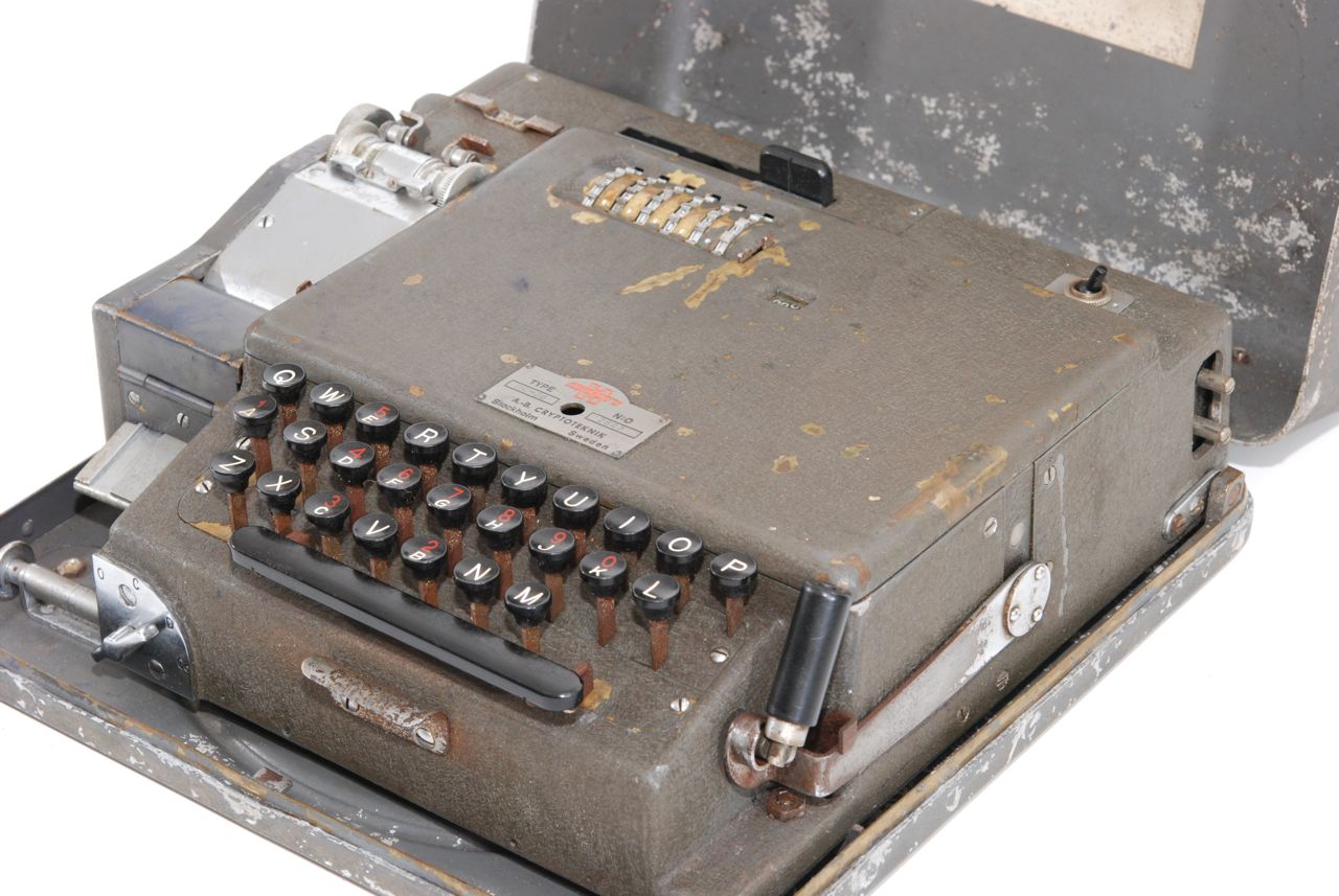
The image on the right shows another example of a BC-38.
This one is also of WWII vintage and from the images below it becomes
clear that this machine has seen some action.
Although it has signs of heavy use, the machine is complete and
in working condition.
It was used by the American Armed Forces during WWII and was found in Norway
shortly after WWII.
It came with the lid of a BC-389 (a slightly modified or improved version).
|
|
|
-
Document kindly provided by
Historische Collectie Verbindingsdienst
via BartW. November 2017.
-
This document describes the Hagelin M-209 and the C-446A in great
detail. Not only is the working principle of the machines explained,
it also discusses the machine's cryptanalysis and methods for its attack.
The document is in Dutch and was released for publication in 2011. 2
-
Released for publication in 2011 by DIVI (Dutch School for Military
Intelligence) [2].
|
|
|
|
Any links shown in red are currently unavailable.
If you like the information on this website, why not make a donation?
© Crypto Museum. Created: Thursday 06 August 2009. Last changed: Wednesday, 24 August 2022 - 20:21 CET.
|
 |

|
|
|