|
|
|
|
|

|
|
← Germany Phone Voice
Speech scrambler
- not in collection
GK-III b was a portable
speech inverter,
or voice scrambler,
developed around 1942 by
Siemens & Halske for
use by the German Army
during WWII.
The battery-powered valve-based device was housed in a standard-size
panzerholz carrying case,
and could be connected to an existing (field) telephone line or radio set.
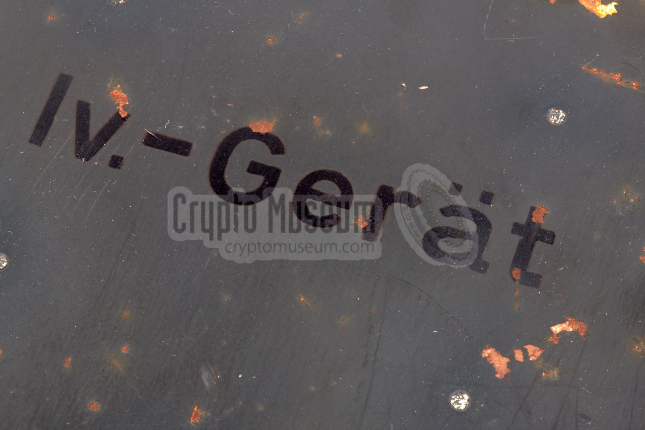
According to the text on the case lid, it is
also known as Iv.-Gerät, 1 which probably means
Invertier-Gerät [1].
The official name is Kleiner Leitungsverzerrer GK III [A].
|
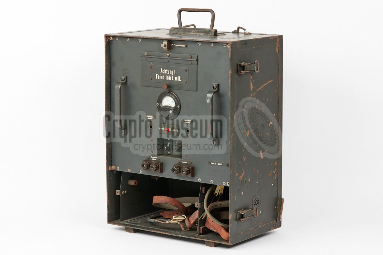
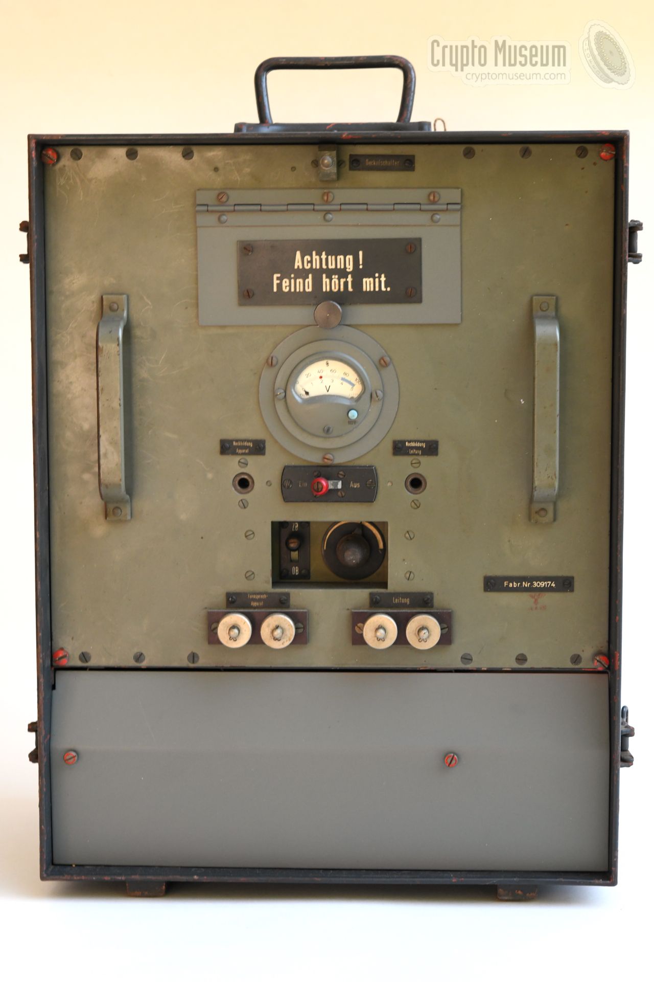
The image on the right shows a typical GK-III b, which is held in the collection
of the Foundation for German Technology CDV & T [1]. It is housed in a typical
panzerholz case – similar to the ones used during the war for German radio
sets and for Hellschreibers –
that could be carried on the back. It has a removable lid at the front, behind which
all controls and connections are located.
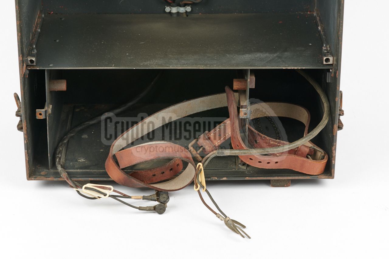
The device is powered by three batteries (-3V, +2V and +90V) that are installed
in the bottom compartment of the case.
The rest of the case (approx. 2/3rd) is
taken by the actual scrambler.
|
|
|
The GK-III uses a simple frequency inversion scheme, based on a fixed
mirroring frequency of approx. 2000 Hz, and is very similar to the
American A3
and the British Frequency Changer,
both of which were used by the Allies during WWII.
The GK-III was used as a safety measure against occasional or (un)intentional
eavesdroppers – such as the exchange operator or a field engineer working
on the lines – but was no match for a professional interceptor. This was
known to the Germans as they themselves were able to solve the British
and American scrambler systems [4].
According to Michael Pröse in [4], the GK-III was used by the German Army
(Wehrmacht), the German Police (Polizei), the Nazi party (NSdAP) and
by various departments of the German State. As most systems were
used over telephone lines, there was little chance of enemy interception.
|
-
Iv.-Gerät = Invertier-Gerät (inversion device).
|
Help wanted —
At present, not much is known about the Siemens & Halse GK-III speech scrambler.
Although it is mentioned in Michael Pröse's dissertation of 2004 [4], the year
of introduction and the production quantities are currently unknown.
We are specifically looking for circuit diagrams and for service documentation,
but any other information would also be most welcome.
➤ Contact us
|
|
Green enclosure
S/N 302174
|
|
|
|
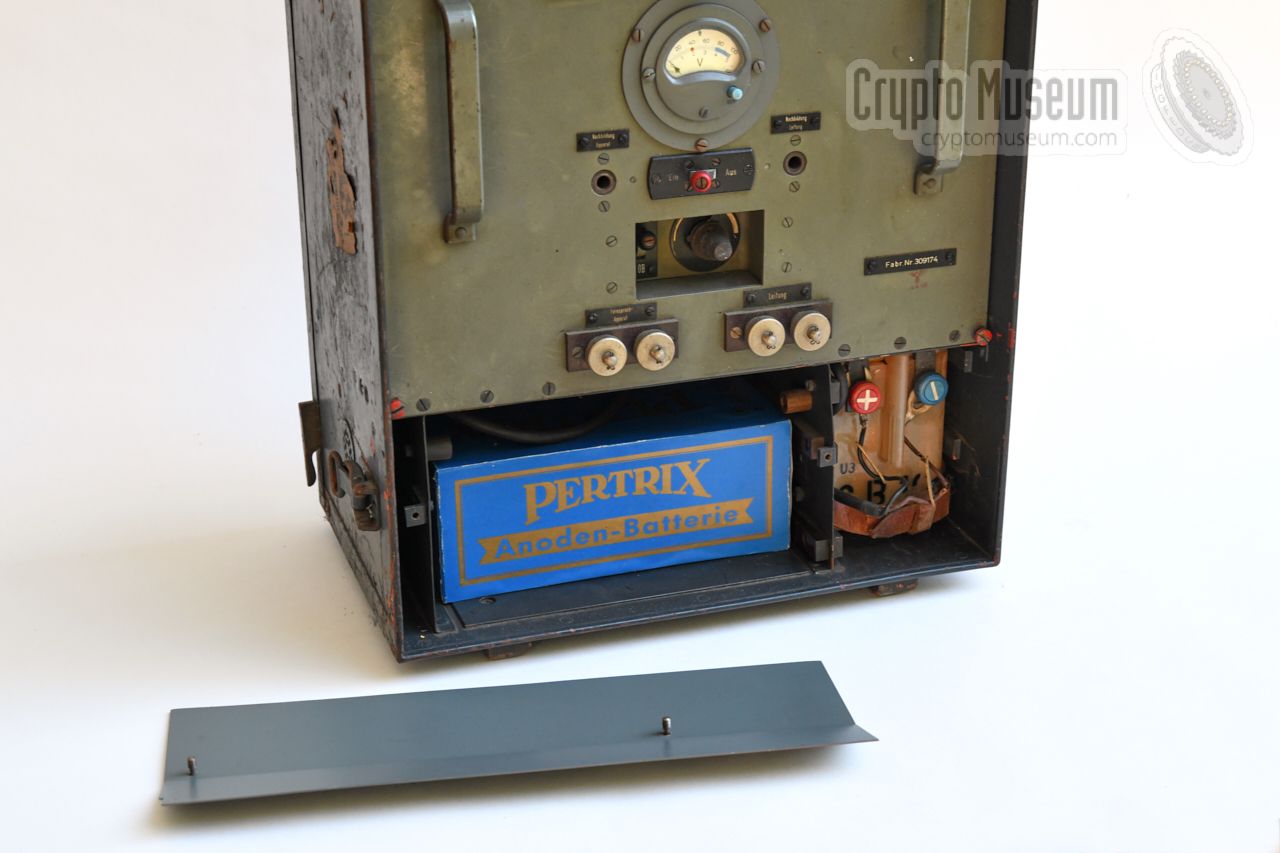
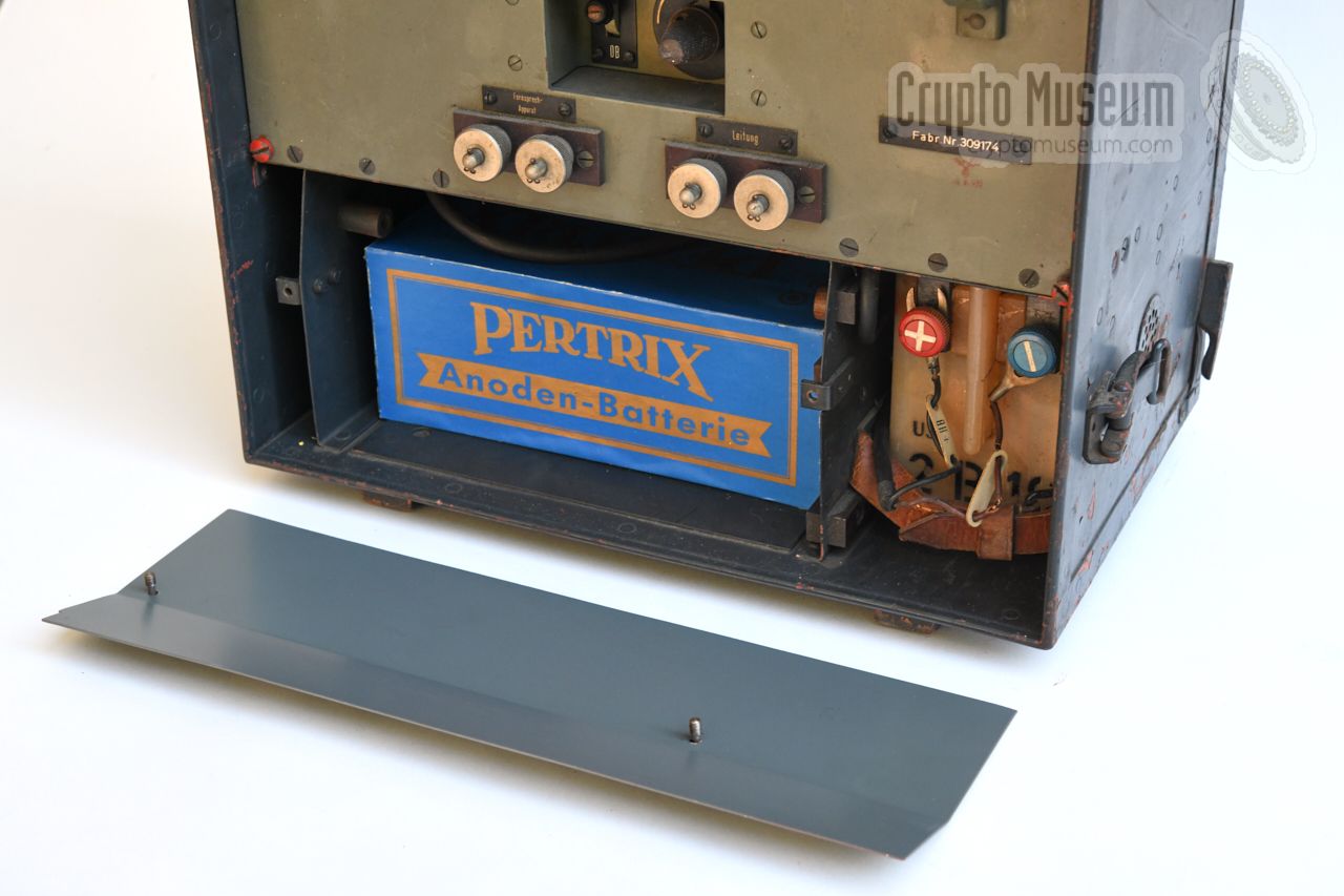
Although the GK-III was normally suppied in a grey enclosure, some were
housed in a green case, such as the one with serial number 302174 [5].
Given the fact that it has the lowest serial number that has so far been observed,
it is likely that it belongs to one of the first series.
The images also show the metal panel
– held in place with two screws –
that covers the battery compartment at the bottom, plus the
LT/HT batteries,
all of which are missing from the device featured above.
|
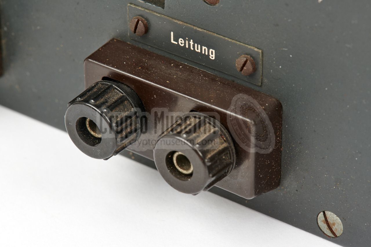
The GK-III was an in-line device, that was connected between a
(field) telephone set and the (field) telephone line.
The diagram below shows the basic setup of a simple point-to-point
connection, with one GK-III b unit connected at either end of a
regular (field) telephone line.
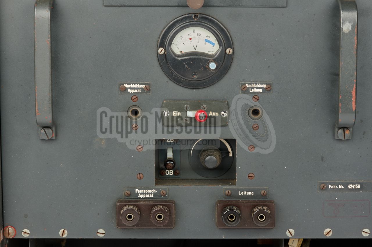
A two wire telephone set was then connected to the Fernsprech-Apparat
terminals of the GK-III. A recessed switch on the
front panel of the GK-III, allowed selection between Local Battery (OB)
or Central Battery (ZB) systems.
Signalling (i.e. the bell/calling voltage) 1
bypasses the system.
|
-
German: Weckspannung (wake-up voltage).
|
Below is the simplified block diagram of the GK-III b, based on the
drawing that was found inside the lid
of the device featured above.
The circuit is pretty straightforward and is very similar to the
British wartime Frequency Changer,
also known as Privacy Set
and later also as Secraphone.
The circuit has two branches: one for transmission and
one for reception. The signal from the connected telephone set (left)
is first filtered, so that only signals in the 0-1900 Hz range
are kept (blue). The resulting signal is then passed to a ring mixer,
where it is added to the 2000 Hz sinewave from a fixed oscillator.
At the output of the mixer, the sum and difference of the two signals
are available, with the difference (red) being the inverted version
of the original signal.
The signal is then passed through another low-pass filter, so that only
the inverted signal (red) is presented at the output (right). The reception
path (i.e. the lower branch) works in a similar way. The inverted signal
(red) is first filtered and then passed to a 2nd ring mixer,
where it is added to the 2000 Hz oscillator signal, after which the sum
and difference are available at the output.
After low-pass filtering it again, the un-inverted signal (blue) is
passed to the telephone set (left).
At the top of the block diagram is a bypass switch that is operated in parallel
with the ON/OFF switch. It ensures that – when the device is switched off –
the telephone set is connected directly to the line. At the bottom is a
mystery circuit that is marked as Umg., which probably means Umgang (bypass).
Although it is currently unclear what this circuit does, it seems likely that
it is used to pass the DC voltage for the carbon microphone in the telephone's
handset directly from the line to the telephone set. This would be needed
in a Central Battery (CB) telephone system.
➤ Printable version of the original block diagram
|
|
The GK-IIIb is housed in a standard panzerholz case that measures
approx. 44.5 x 36 x 22 cm and weighs no less than 25 kg (without the batteries).
The interior can be accessed by loosening four large (red) bolts
at the corners of the front panel, and using the two large grips to extract
the metal frame with the electronics from the case.
All circuits are mounted to the front panel.
|
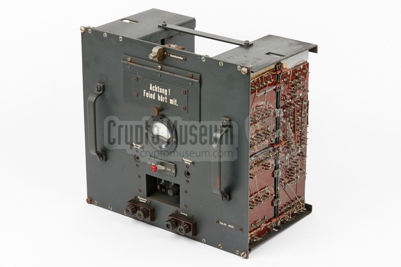
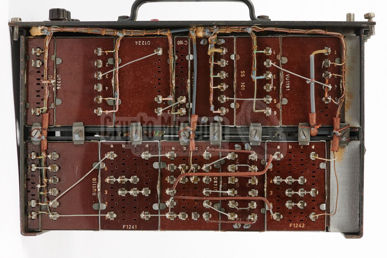
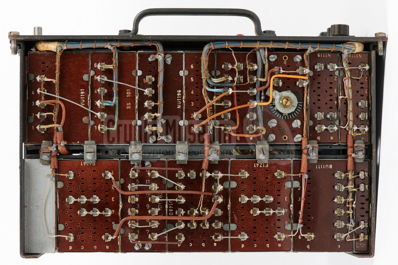
Looking at the interior from the rear,
the frame can roughly be divided into
three sections: the receiver at the left,
the transmitter at the right and
the valves (tubes), controls and connections
at the centre. The transmitter
and receiver each consist of a series of shielded (metal) modules of which
the terminals are visible from the outside.
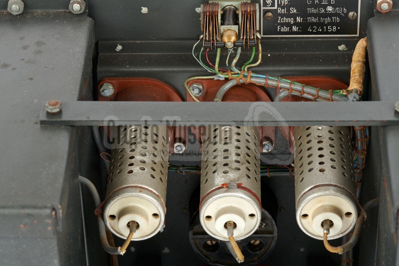
The circuit is build with just three RV-2P800 valves (tubes): one for the
2000 Hz oscillator, and one for each of the audio amplifiers. The rest of the
unit consists of passive parts, like resistors, capacitors and
many low-pass filters.
|
|
|
|
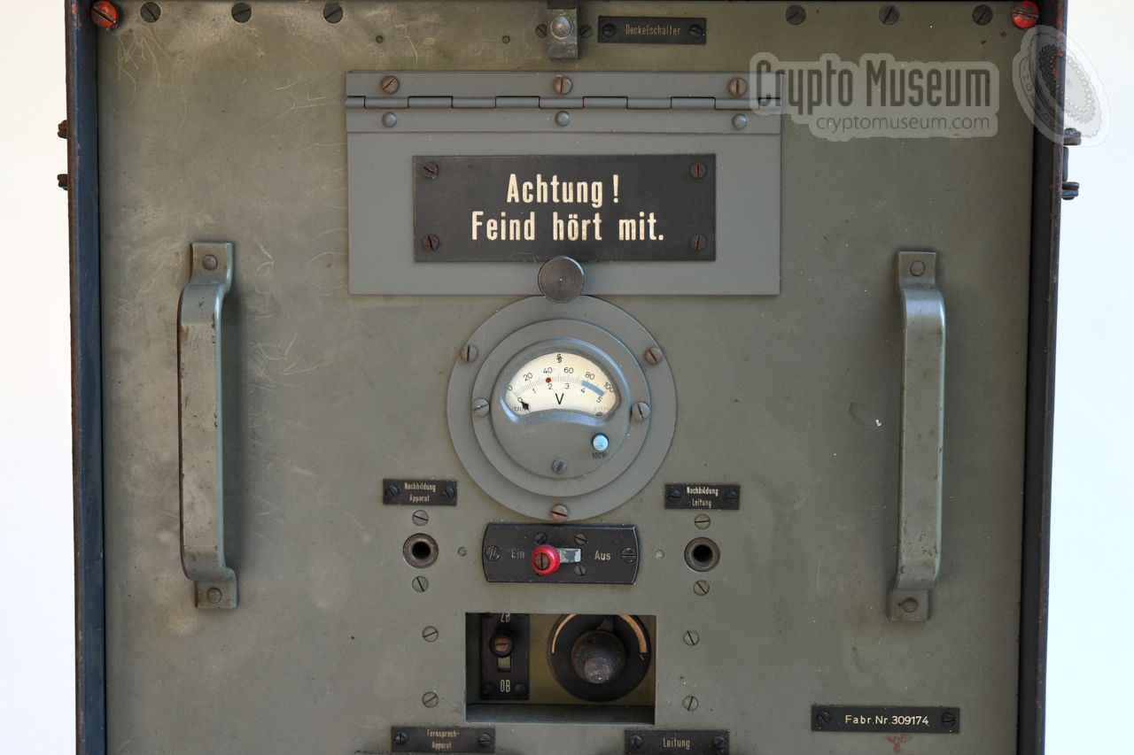
At the centre of the upper edge of the front panel is a
push-button (shown below)
that detects whether the lid of the panzerholz case is in place.
According to the metal tag, this is the Deckelschalter (lid switch).
It ensures that – when the case is closed – all battery wires are disconnected.
|
The image on the right shows a close-up of the lid switch, which consists of four
individual sets of contacts. Two power lines (+2V and +90V) are also routed
via the ON/OFF switch.
When OFF, the telephone set is connected directly to the line. In the ON position,
power is applied to the circuits and the phone is routed via the device.
The RV-2P800 valves are mounted at the centre
of the device, behind the front panel, in such a way that they can be
accessed through a hinged lid at the front.
As the extra safety measure, the lid holds an
eavesdropping warning message.
|
|
|
The mixers are made with very early GL-101/6 copper-oxide rectifiers (diodes) [2] –
made by Siemens
– of which four are used in each mixer. On his website
CDVandT.org,
Arthur Bauer shows
that in the GK-IIIb he obtained in early 2019, these diodes were
all gone, probably due to ageing of the material. They could simply be replaced
by four small signal diodes (e.g. 1N4148) [1].
➤ More on Arthur Bauer's website (off-site)
|
Device Voice scrambler Purpose Telephone privacy Principle Audio band frequency inversion Model GK-III b Manufacturer Siemens & Halske Country Germany Year 1942 Carrier 2000 Hz ± 50 Hz Valves 3 × RV-2P800 Power -3V, +2V, +90V Batteries HT 0-3V-90V, LT 2B19 Dimensions 460 × 360 × 230 mm Weight 25 kg (32 kg with batteries)
|
|
The serial number of the GK-IIIb is usually engraved in a metal plate that
is fitted at the front panel (at the bottom right). Furthermore, a tag with
the full production data can be found at the
inside of the front panel,
close to the upper edge. The following data is available:
|
|
It is currently unknown how many GK-IIIb units were manufactured.
In order to get an indication of the production quantity, we would like
to capture as many serial numbers as possible. So far, the following
serial numbers and acceptance stamps have been observed:
|
302174 unreadable Private collector, Austria (green case) 423988 Wa.A. 577 Private collector, Austria 424028 ? CDV&T, Netherlands 424158 Wa.A. 577 CDV&T, Netherlands
|
|
OB
|
|
Orts-Batterie
Local battery system. In English known as LB.
|
|
Umg.
|
|
Umgang
Bypass (not confirmed).
|
|
ZB
|
|
Zentral-Batterie
Central battery system. In English known as CB.
|
-
Document kindly provided by Günter Hütter [5].
|
-
Document kindly provided by Arthur Bauer [1].
|
|
|
|
Any links shown in red are currently unavailable.
If you like the information on this website, why not make a donation?
© Crypto Museum. Created: Monday 29 April 2019. Last changed: Wednesday, 05 November 2025 - 11:48 CET.
|
 |

|
|
|


![GK-III ring mixer. Photograph courtesy Arthur Bauer [1].](img/gk3b_mixer_thumb.jpg "image # gk3b_mixer.jpg")


![GK-III ring mixer. Photograph courtesy Arthur Bauer [1].](img/gk3b_mixer.jpg)