|
|
|
|
|

|
Video-over-radio system
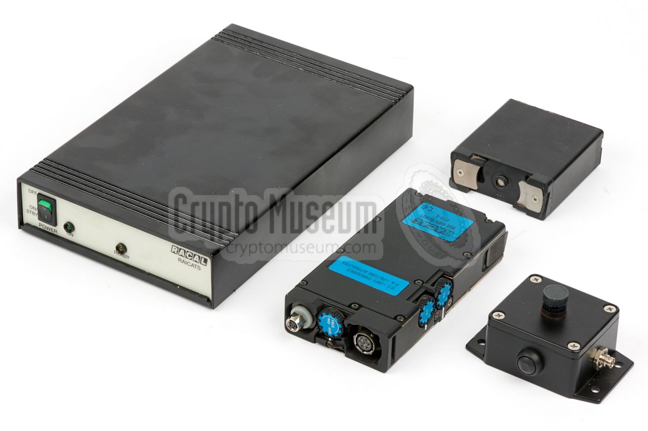
RAICATS 1 is a video-over-radio (VOR) transmission system for
simplex or half-duplex
VHF/UHF radio,
developed around 1996 by
RACAL in Salisbury (UK), as part
of the Cougar Radio portfolio.
It was intended for covert use,
and offers various baudrates, compression ratios and resolutions.
Real-time video processing is achieved by means of Digital Signal
Processing (DSP) technology.
|
The portable ITU-C is housed in a die-cast aluminium enclosure, that is nearly
identical to that of the
Racal Cougar PRM-4515 portable radio.
It was designed for use on EPM 2 channels, with a 16 kbps capacity, and
was claimed to be highly error-resilient. It allows high-quality video images
to be sent via a low-bandwidth radio channel to a base station, where they
can be displayed on a PC [2]. For enhanced security, the device was often
used in combination with an encryption system.
After Racal
was taken over by Thomson (now: Thales)
in 2000, the company used RAICATS as a technology demonstrator for future
video systems [2].
In 2014, some remains of the RAICATS project ended up on the surplus marked,
and devices were offered on auction sites like eBay.
|
-
RAICATS = Racal Imagery Compression and Transmission System.
-
EPM = Electronic Protection Methods [2].
|
-
Mutually exclusive. At the transmitting end, either an ITU-R or an
ITU-C is used.
|
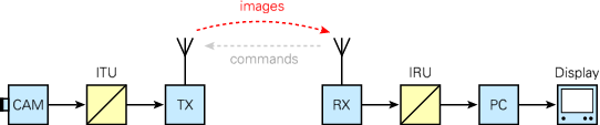
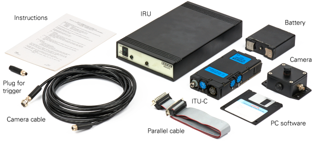
The diagram below shows how and where in the chain the units are used.
At the left is the remote image transmitting station.
It consists of a camera (CAM), an
Image Transmitting Unit (ITU)
and a transceiver (TX). At the right is the
image receiving base station, which consists of a transceiver (RX), an
Image Receiving Unit (IRU)
and a MSDOS Personal Computer (PC) with a (colour) display.
Depending on the configuration and the (internal) settings,
the base station
can send commands to the remote station, to alter the latter's settings and
to request one or more video images. Alternatively, the remote station can
be configured to generate a constant stream of images. In addition each
station can be given an address (1-31), so that it can be accessed
individually.
|
- OFF
Standby Waiting for over-the-air command Active Transmitting images Sleep Powered down, waiting for trigger (button)
|
|
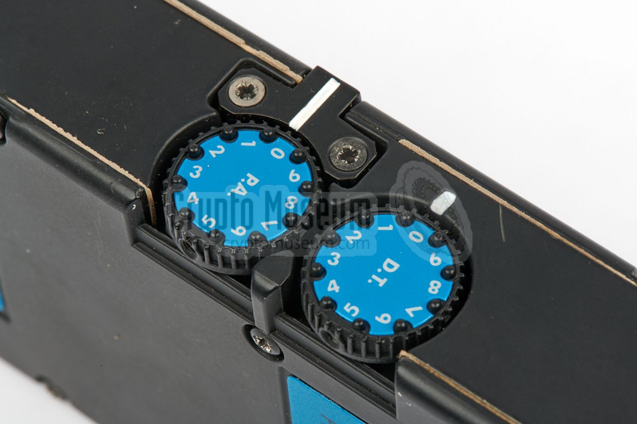
This setting defines the amount of detail of the image (resolution) as well
as the compression ratio. There are 10 possible settings (0-9), of
which the first five (0-4) have the lowest resolution (128 x 128 pixels),
wehereas the last five (5-9) provide the highest resolution (320 x 240 pixels).
A higher setting means more detail (i.e. less compression),
at the cost of a lower refresh rate.
|
|
The system has two ways of updating the picture: (1) ALL, which means that
the whole image is transmitted, and (2) UPDATE, which means that only the
areas which have changed from the previous image are transmitted.
When in UPDATE mode, the DT-setting can be used to specify the Difference
Treshold (DT), which is the amount of change before the image is transmitted.
|
-
The PRM-4515
was available in a VHF-L, VHF-H and UHF variant.
|
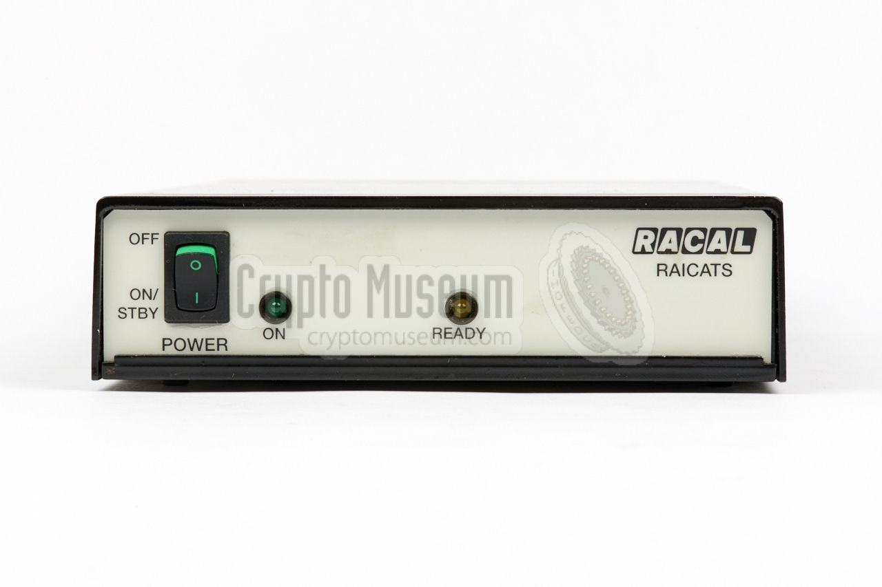
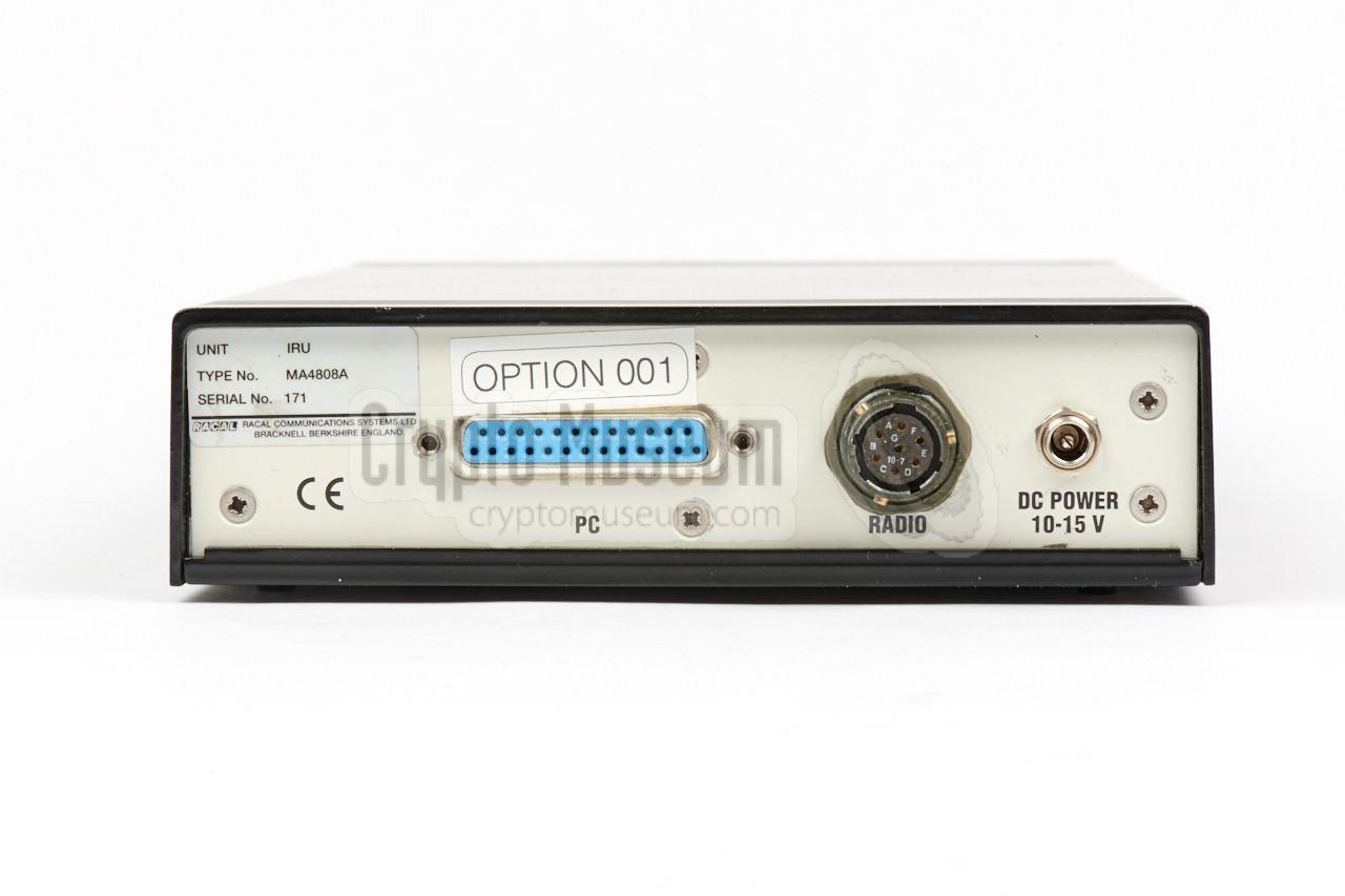
At the receiving end (i.e. the base station) the desktop unit –
shown in the image on the right – is used for transferring the
images from the radio (receiver) to a connected PC. Software for
an MSDOS compatible computer is provided.
The device is effectively used as a MODEM.
The IRU is connected to the parallel port of an MSDOS PC,
by means of the provided
25-way (DB25) ribbon cable.
|
|
|
|
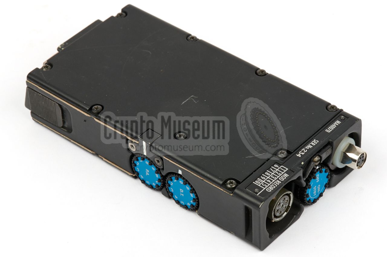
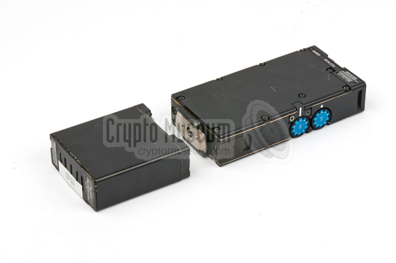
For field use – also known as covert use –
the portable modem shown in the image on the right, was used at
the transmitting side. It is housed in a die-cast aluminium enclosure,
that is very similar to that of the
Racal Cougar PRM-4515 portable radio.
|
|
|
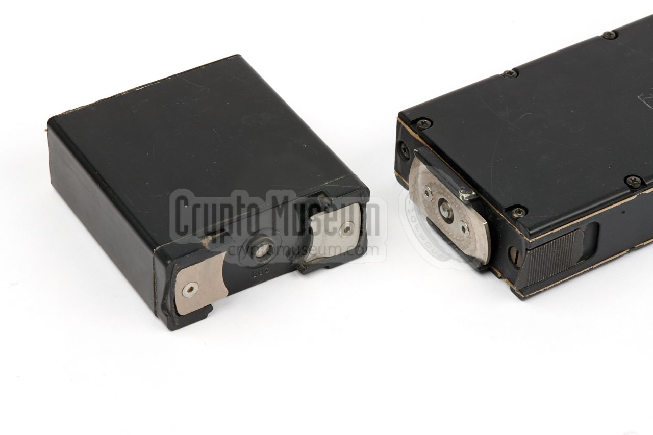
The portable ITU-C unit was powered by the same batteries as the
Racal Cougar PRM-4515,
which was attached at the bottom of the unit.
The battery is available in several sizes, with varying capacities.
Most batteries were re-chargeable, but there were also versions that
accepted (consumer market) AA-size dry cells.
|
|
|
The image on the right shows the video camera that was supplied with the set.
It consists of a small rectangular aluminium enclosure with 4 mounting
holes at the bottom, allowing it to be affixed to, say, a uniform or a soldier's
webbing.
The camera is at the front. When it is not used, the lens can be protected by
a plastic cap. At the sides are sockets for
connection to the ITU
and to an (optional) external trigger button.
|
|
|
|
This short ribbon cable was provided for connecting the IRU modem
to the parallel port of the PC – also known as the printer port or the
Centronics port. At the time, printers were generally connected via
a DB25 connector.
|
|
|
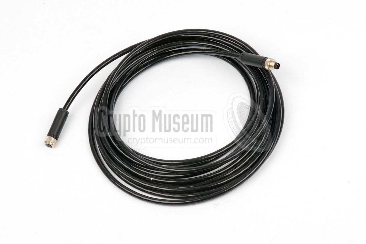
A shielded cable is used for connection of the camera
to the ITU.
The cable has a 4-pin male plug at one end,
and a 4-pin female plug one at the other end.
The cable shown here is approx. 3 metres long, but for body-worn applications,
a cable of one metre was usually sufficient.
|
|
|
A 3.5" floppy disc was supplied, with suitable software for a
66 MHz 486 Personal Computer (PC) with MSDOS 6.2 or later.
It provides remote control of the ITU and its camera,
and allows the received images to be displayed on the screen.
The latest known software version is 1.0, released on 5 February 1996.
It is available for download as a ZIP-compressed image below.
➤ Download the software
|
|
|
|
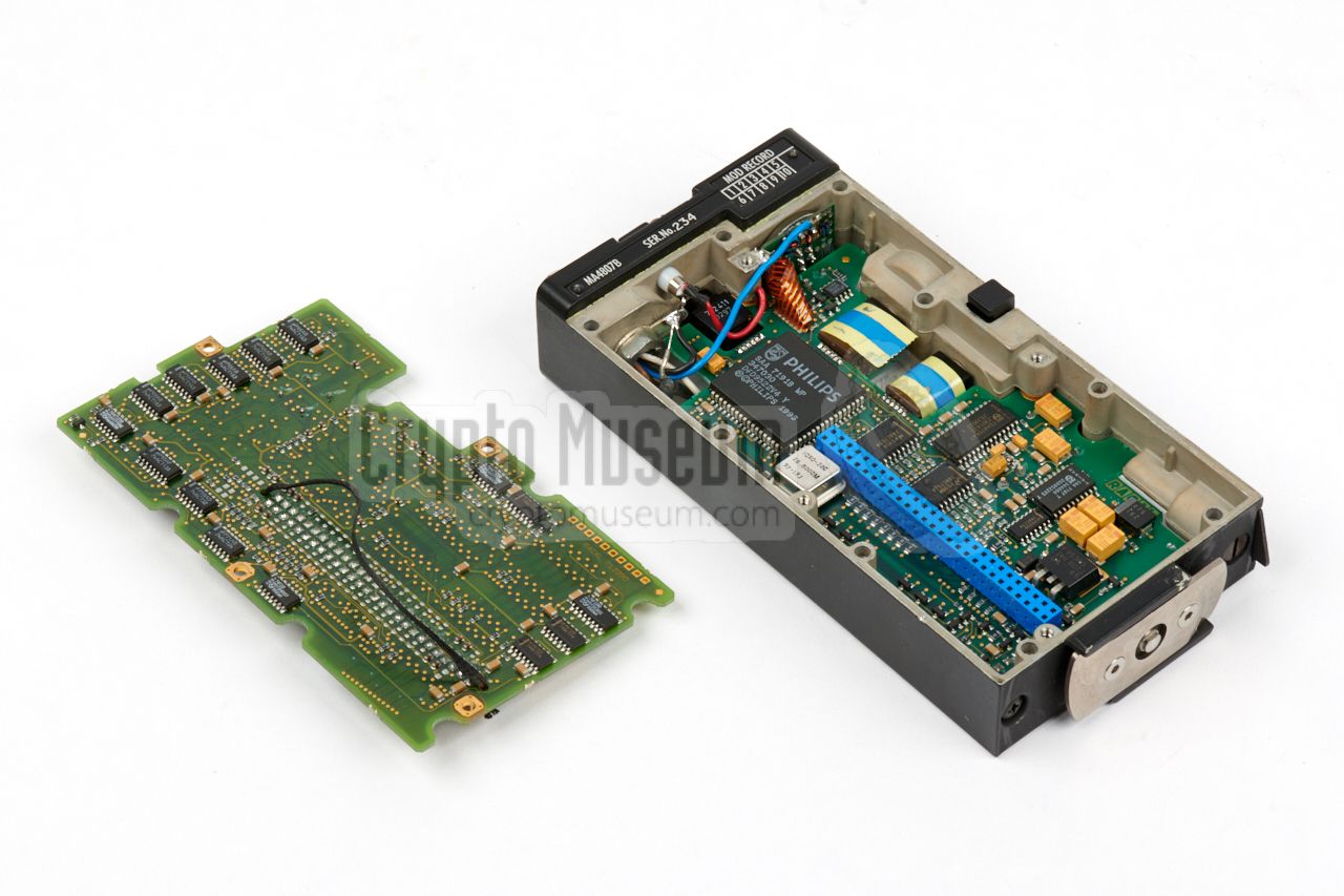
The ITU-C is built to high production standards, similar to the
Racal Cougar PRM-4515 handheld radio.
The interior is accessible from both sides, by removing
the front and rear panels, each of which is held in place by 9 recessed
screws. After loosening them, the panels can be removed.
|
|
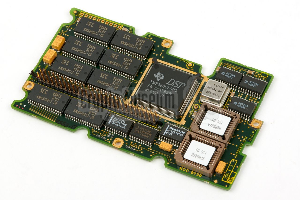
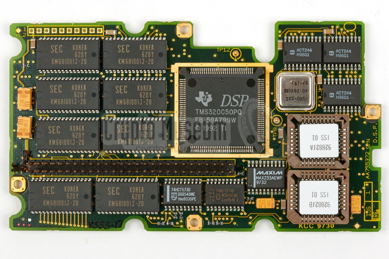
The DSP board is slotted into the
large blue 54-pin female socket
on the interface board, which is clearly visible in the image above.
Apart from the TMS320 DSP, it also holds the RAM memory
and two two EPROMs with the firmware. According to date codes on some
parts, it was made in 1997.
|
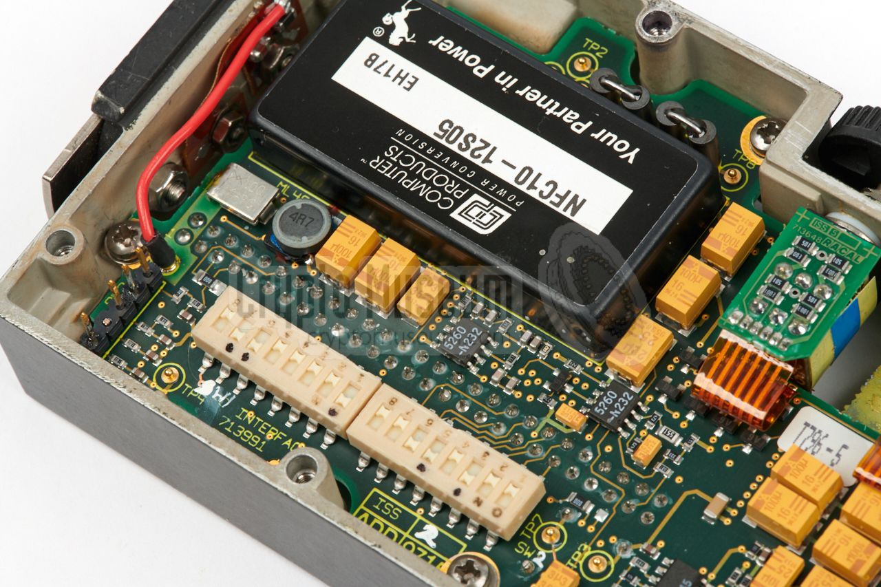
The IRU (and also the ITU-R) is larger and more conventionally built.
It is housed in a rectangular die-cast aluminium enclosure that is intended
for desktop use. It's interior is accessible from the bottom, by removing
eight recessed screws and taking off the bottom panel, as shown here.
Inside the case is just one PCB with components at both sides.
It holds the radio interface, a DSP processor — the same one as used in
the ITU — and a parallel interface to the PC. Looking at the PCB and the
unpopulated space, it is evident that it was also used as the base
of the ITU-R unit.
|
|
|
|
At the center of the board are two (colourful) DIP-switch arrays (marked
SW1 and SW2) that are used for setting the internal configuration.
They correspond to the two DIP-switch arrays inside the ITU,
and should be set identical. The function of each switch is
described in a table below.
|
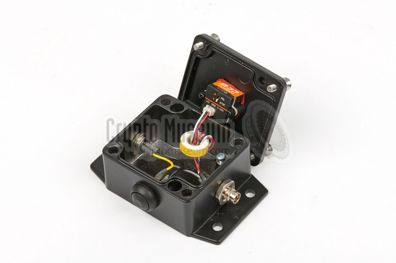
Although the camera is arguably one of the most important parts of the kit,
it is also the simplest part. It is housed in an off-the-shelf die-cast
aluminium enclosure with four mounting holes.
At the top is a lid that is held in place by four large recessed screws.
The interior can be accessed by removing these screws. Inside the box is
not much more than a single-piece universal camera module that is mounted
to the inside of the top lid, with its lens protruding it. It is sealed to
make it water-resistant. Just three wires are needed for connecting the
camera.
|
|
|
|
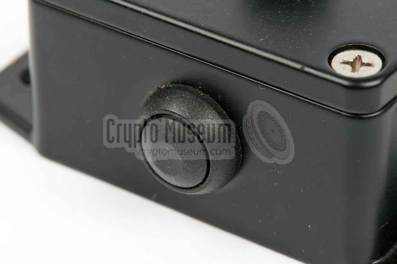
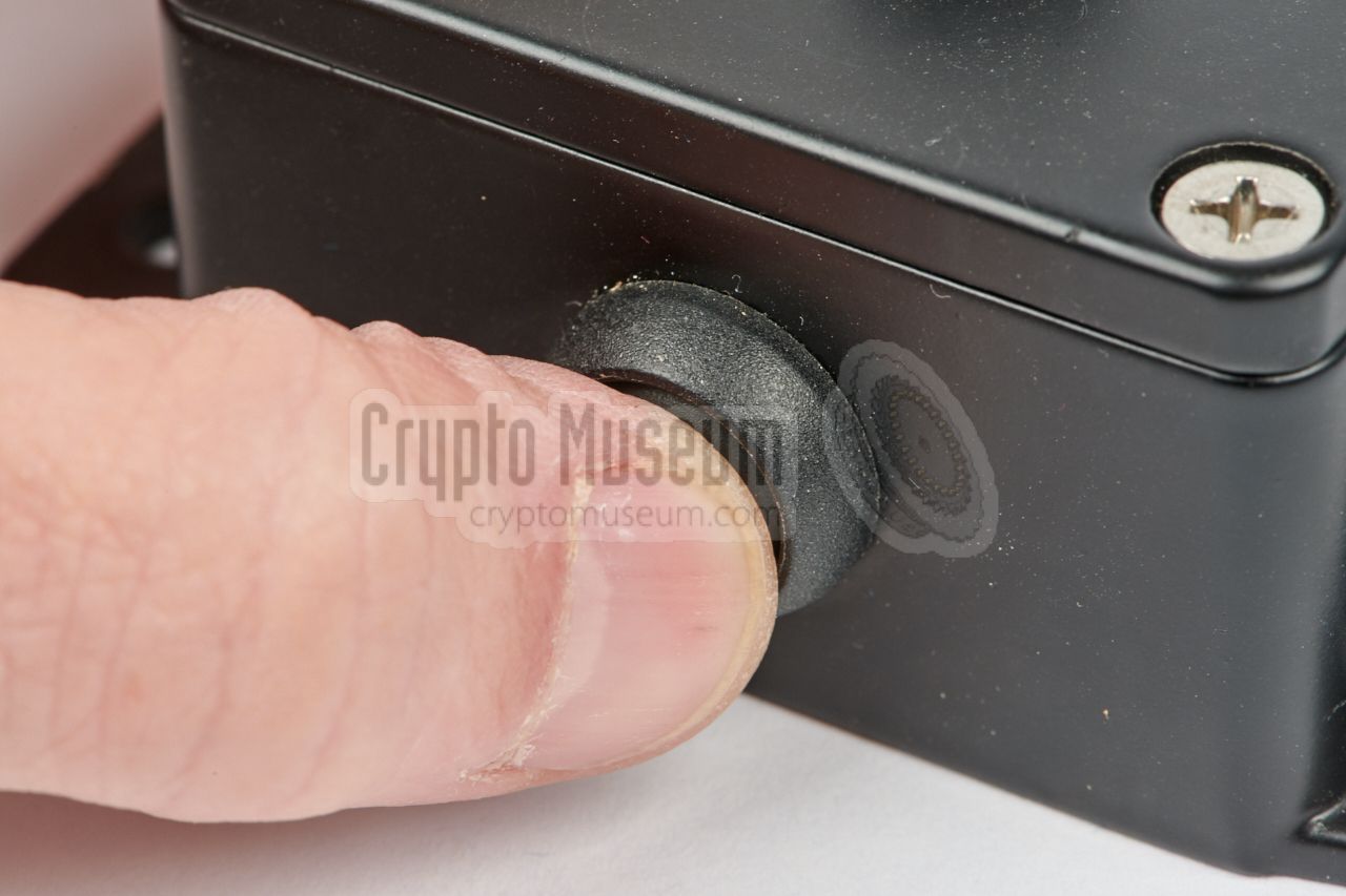
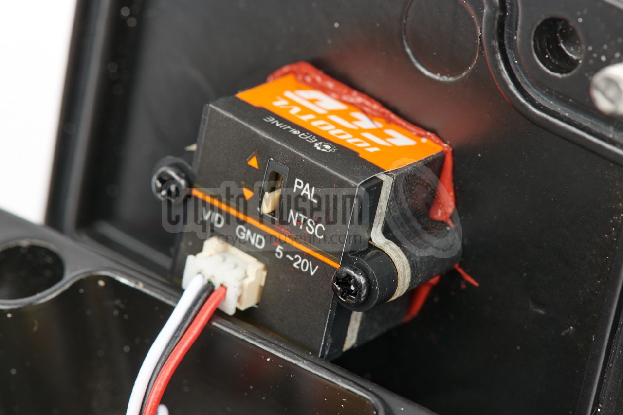
The camera is wired directly to the 4-pin female socket
mounted at one of the sides. At the other side is a
3-pin male socket that can be used to connect
an (optional) external trigger switch, that is wired in parallel with the
black trigger button
that is present on the front of the camera body.
|
|
The recessed 7-pin female Clansman-style 105 socket at the
top panel of the ITU-C,
is used for connecting the device to a suitable
VHF/UHF radio.
It is wired as per Clansman
standard, which is also supported by the later
Bowman system.
A Cougar/Clansman radio is wired as follows:
|
- Mic or Fixed Level Audio (FLA) or program input
- Mic return or Wideband programming
- Power in or out +10V (current out ≤ 100 mA)
- Audio/Data (AF out 400mW into 8Ω)
- Ground
- PTT or 4 kb/s data or key fill data
- Squelch or CTS
|
|
|
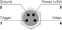
Below is the wiring of the 4-pin female camera socket on the top panel
of the ITU-C, when looking into the socket. The 4-pin male socket on the
body of the camera, is the mirrored version of the one shown here. The
camera should be connected to the ITU by means of a 1:1 cable, of which at
least one wire (4) must be shielded, as it carries the video signal.
|
- Trigger (switches to ground)
- Ground (0V)
- Power (+5V)
- Video 1Vpp NTSC
|
|
|
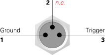
On the camera body are two sockets: a 4-pin male one for connection to
the ITU (see above) and a 3-pin female one for connection of an external
trigger button. When used, it must be connected to ground in order to
cause a trigger. This means that the outer two pins should be shorted.
|
- Ground (0V)
- not connected
- Trigger (switches to ground)
|
|
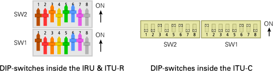
Inside the the transmitting and receiving units, are 16 DIP-switches that define
the configuration. The switches are arranged as two sets of 8
DIP-switches each. The sets are marked SW1 and SW2 and are arranged as shown
in the diagram below. At the left are the switches that are present on the
top side of the PCB
inside the IRU and the ITU-R.
At the right are the switches that are present on the
top side of the interface board
inside the ITU-C.
Both sides must be configured identically.
|
- Address bit 0
- Address bit 1
- Address bit 2
- Address bit 3
- Address bit 4
Baudrate bit 0 00 = 16 kb/s, 01 = 12 kb/s, 10 = 8 kb/s, 11 = 1200 baud - Baudrate bit 1
Picture mode OFF = all, ON = difference 1
|
-
Should always be OFF to allow control from front panel swiches.
|
Preamble time OFF = 100 ms, ON = 400 ms RX/TX delay bit 0 00 = none, 01 = 200ms, 10 = 500ms, 11 = 2s - RX/TX delay bit 1
Squelch priority OFF = disable, ON = enable Link type OFF = half-duplex, ON = simplex Display colour OFF = colour, ON = Monochrome - -
- -
|
| Model | Name | Description |
|
|
| MA-4807/A | ITU-R | Desktop transmitting unit |
| MA-4807/B | ITU-C | Covert transmitting unit |
| MA-4808/A | IRU | Receiving unit |
| MA-4516W | Battery | Battery for ITU-C |
| 611647 | PSU | Mains PSU for IRU |
| 611950 | Software | 3.5" floppy with PC software |
|
Radio 16 kbps compatible radio Connector US Style U238/U Requirements 66 MHz 486 PC with parallel port and MSDOS 6.2 or later Interface Parallel (DB25) Power 10 — 15V DC (typically: 12V DC) Dimensions 255 x 155 x 45 mm Weight 1472 grams
|
Video input Composite video 1V-pp, NTSC, 75Ω Compression Variable, 9 settings Resolution 128 x 128 or 320 x 240 pixels Radio 16 kbps compatible radio Modem 2400, 9600, 14400 or 19200 baud Refresh rate 1 second (128 x 128) or 5-8 seconds (320 x 240) Connector US Style U238/U Power 10V DC battery (MA-4516 or equivalent) Temperature 0°C — +40°C (storage: -10°C — +55°C) Dimensions 159 x 75 x 30 mm (with battery: 236 x 75 x 30 mm) Weight 488 grams (without battery)
|
|
DT
|
|
Difference Treshold
In this context, its means the difference between the current picture
and the previous one. It allows the system to limit the amount of data
that is sent over the radio link, by only sending the differences.
➤ More
|
|
EPM
|
|
Electronic Protection Methods
Expression - frequently used by Thales
- for a radio channel that has been secured by means of electronic measures,
like encryption (CRYPTO)
and/or frequency hopping (FH).
Also known as ECCM.
|
|
IRU
|
|
Image Receiving Unit
Desktop modem used at the receiving end of a RAICATS video link.
|
|
ITU-R
|
|
Image Transmitting Unit Radio
Desktop modem used at the transmitting end of a RAICATS video link.
|
|
ITU-C
|
|
Image Transmitting Unit Covert
Portable modem used at the transmitting end of a RAICATS video link
in covert operations. ITU-C is an alternative to ITU-R.
|
|
NTSC
|
|
National Television Standards Committee
Analogue composite video standard that was (mainly) used in North America,
from 1954 until 2010, when it was dropped in favour of digital systems.
Incompatible with the PAL and SECAM standards that were used throughout
Europe.
➤ Wikipedia
|
|
PA
|
|
Picture Attributes
In this context, it is used to describe the properties of the video
signal, in particular the resolution and the (lossy) compression ratio.
➤ More
|
|
RAICATS
|
|
Racal Imagery Compression and Transmission System
System for sending video over a VHF or UHF radio channels with limited
bandwidth.
|
|
VOR
|
|
Video over Radio
System for sending video images (stills or moving) over a radio link.
|
|
|
|
Any links shown in red are currently unavailable.
If you like the information on this website, why not make a donation?
© Crypto Museum. Created: Wednesday 09 January 2019. Last changed: Tuesday, 05 February 2019 - 12:19 CET.
|
 |

|
|
|
|