|
|
|
|
|

|
|
Bugs Wire tapping CIA NRP EC RC →
The device consists of three units: a transmitter,
a line interface
and a receiver.
The transmitter impresses a carrier signal well above
the audible range onto the telephone line. Part of this signal reaches
the telephone set where, by the virtue of coupling between
the internal parts, some of it reaches the terminals of the
carbon microphone.
Some of the carrier energy will be absorbed by the carbon microphone
and the remainder will be reflected, subject to the instantaneous
value of the microphone's resistance, which changes as a result of
acoustic signals in the target area.
|
|
|
A fraction of the reflected signal travels back through the telephone line,
where it is picked up at the tapping point by a sensitive receiver inside
the WEC.
In order to separate the received signal from the (strong) transmitted
carrier signal, a hybrid duplexing unit is present in the WEC.
The line interface is responsible for an optimum impedance matching
between the WEC and the line. This is done to avoid losses and to
reduce the chance of detection by means of TDR equipment.
|
In 1961, a new type of Easy Chair Passive Element (PE) was introduced, that
could be connected to the telephone line inside the target building. It was
powered by the RF signal from the WEC unit, and delivered its reflected
signal via the telephone line back to the unmodified receiver of the WEC,
where the original audio was recovered. This project was known as
Rocking Chair (RC)
[D].
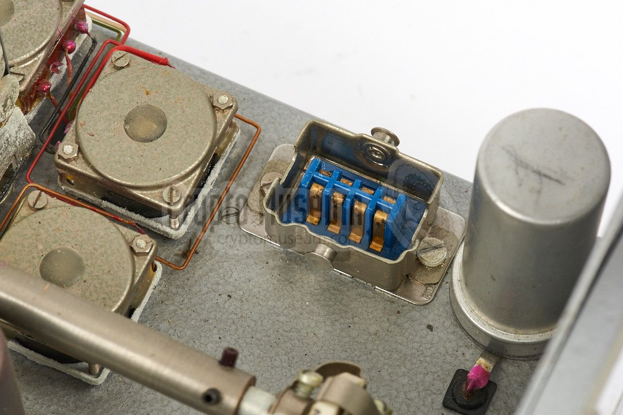
In 1963, the WEC system was upgraded with several extensions, most of which
were intended for specific CIA targets. A line-switching unit was added to
allow the monitoring equipment to switch smoothly between any of 10 telephone
lines, using an optical LDR-based switcher. In addition, the ability was
added to remotely control and monitor the system, via a regular telephone line.
|
-
WEC is the abbreviation of Wired Easy Chair.
|
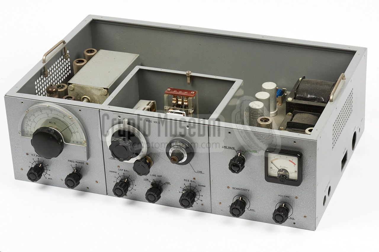
The diagram below gives a good view of the controls and connections.
The device consists of three removable units that are mounted in a
frame: a transmitter (left),
a line interface (centre)
and a receiver (right).
The transmitter has a frequency range of 20 to 300 kHz, divided over
three bands, and has an adjustable power output.
The device has a built-in mains power supply unit (PSU) that is part
of the receiver (right). It is suitable for 110 and 220V AC mains networks.
A socket for connection to the AC mains is located at the right side panel.
Next to it, is a socket on which the receiver's audio output is available.
At the top of the device is a three-pin socket for connection to the
telephone line. It connects to the (twisted) wire pair, commonly
known as the A and B lines, and to ground. Once connected to the phone line,
the line interface (centre) should be tuned for the best possible impedance
matching to the line, in order to maximise the amount of energie that is
coupled into the line, and minimise the chance of detection by a sweep team.
|
- 20 - 50 kHz
- 50 - 120 kHz
- 120 - 300 kHz
|
The application of the WEC is limited to those situations were a
regular (analogue) telephone set is present in the target area,
which is connected to the exchange of a Public Switched
Telephone Network (PSTN), somewhere outside of the target area.
Furthermore, it is necessary that a tapping point can be made
inconspicuously on the line between the target area and the exchange [B].
The diagram above shows how this works. The tapping point can be
made at an existing junction box, in a building where the cable
passes through, at the exchange, at an underground cable joint,
or by digging up the cable and cutting into it.
For situations where it was difficult to access and operate the WEC at
the tapping point unobtrusively, a remote control unit was developed.
The diagram above shows the additional remote control unit (RCU) at
the bottom left. It is connected to an extra telephone line that is
connected to a remote listening post (LP). The WEC unit can be
controlled via this telephone line which also delivers the intercepted
audio at the LP.
|
The block diagram below shows how the WEC unit works. At the left is
the transmitter of which the frequency can be adjusted between 20 and
300 kHz, divided over three bands. Furthermore the output power of the
transmitter is adjustable in order to minimise the chance of detection.
At the right is the receiver, which consists of a band-pass filter,
several amplifier stages, a detector and an audio amplifier. Transmitter
and receiver are both coupled to the same line, via the duplexer
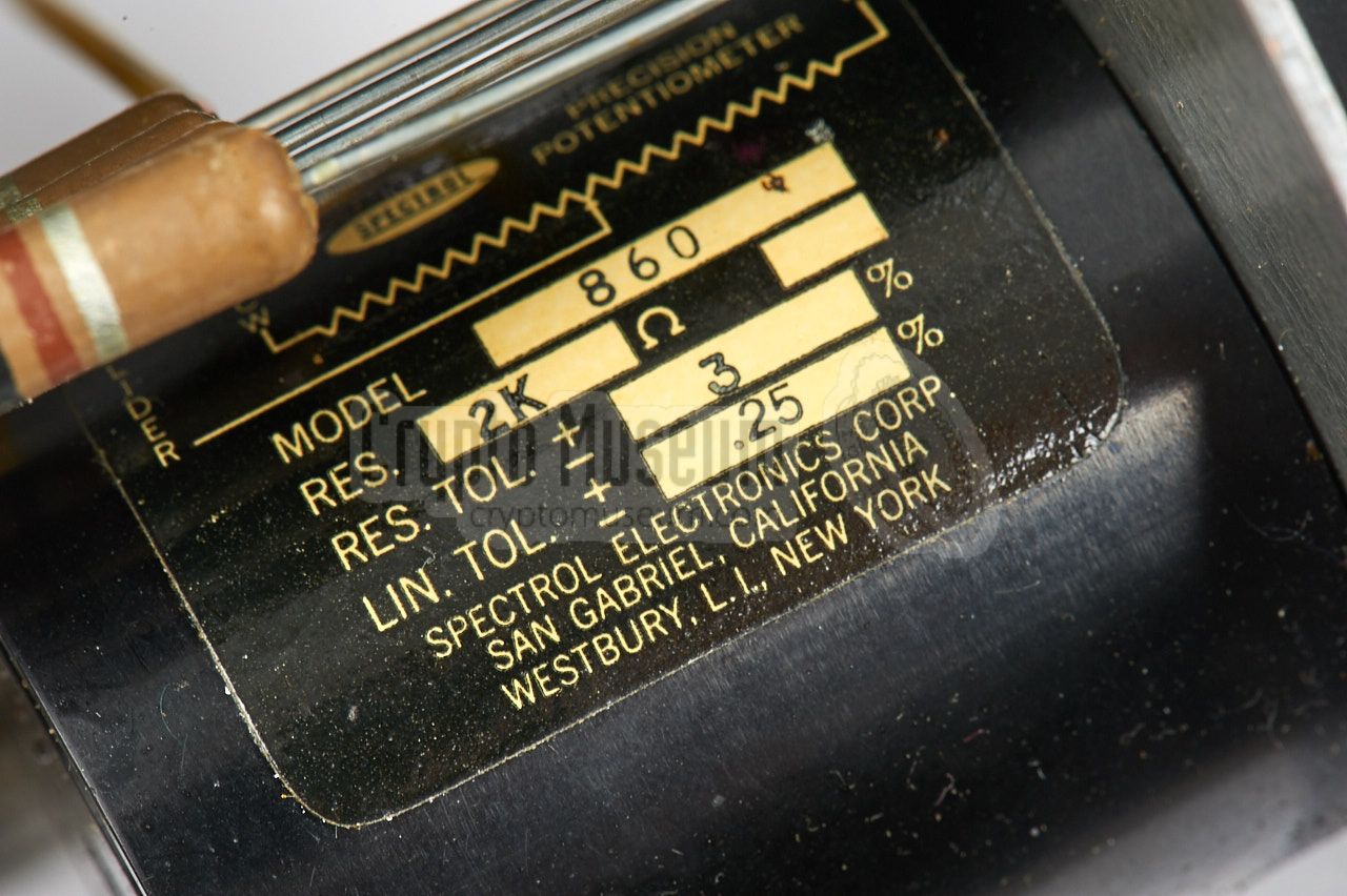
at the centre. This is a bridge-type circuit with adjustable resistors
and capacitors, to achieve an optimum matching to the line.
This is necessary, as in practice the line impedance can vary wildly
under different circumstances, such as line-length and carrier frequency.
|
|
The WEC Mark I was usually carried around in a common unobtrusive green
Skyway travel suitcase that measures approx. 62 x 43 x 19 cm.
The WEC unit fitted nicely inside this suitcase and was held in place by
four wooden blocks in the corners. The remaining space was used for storing
the cables, whilst the manual was stowed in the pocket inside the top lid.
|
|
|
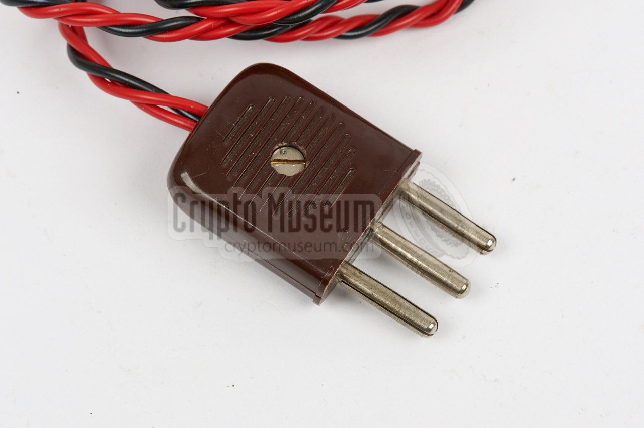
At the right side of the device is a two-pin (3-contact) socket for connection
of the mains power cable, shown in the image on the right.
The plug at the device side of this cable is typical for the era and was
commonly used on domestic appliences such as vacuum cleaners and electric
clothes irons. The plug at the other side of the cable has to fit a wall
socket. It is shown here with a typical European (Dutch) wall plug.
Note that the correct mains voltage (110 or 220) has to be set with the
voltage selector first.
|
|
|
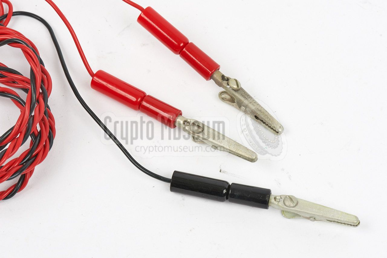
This 3-wire cable was used to connect the WEC to a telephone line.
The wires are twisted in order to maintain the balanced nature of telephone
lines. The 3-pin plug should be connected to the socket on top of the device.
At the other side of the cable are three crocodile clips for connection
to the wires of the telephone line. The black clip is for connection to ground.
The two red clips are for the A and B wires.
|
|
|
|
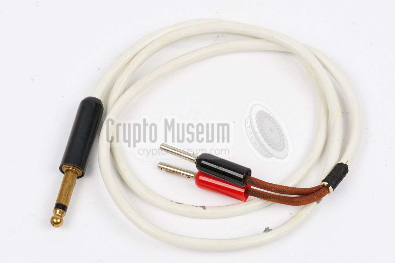
Audio output from the receiver is available on two 6.3 mm jack busses
at the right front of the device. The adapter cable shown in the image on
the right is provided for connection to an amplifier or a recorder.
|
|
|
|
Early tests with prototype WEC equipment in the early 1960s had shown that
the performance of the system depends largely on the targeted telephone set.
At the time, all analogue telephones were built around a
transformer, several capacitors and a handset with a carbon microphone.
|
The actual circuit itself varied between brands and models.
In some phones, at least one of the terminals of the carbon element was
connected directly to one of the line wires, whilst in others they were not.
Furthermore, the microphone signal was often cut-off by the dial interruptor.
WEC was first tested with two phones that were commonly
used in the Netherlands: Heemaf and Ericsson. The Ericsson one gave the best
results, as it could be used without any modifications to the set. Its
performance could be improved by adding a capacitor, but this was not mandatory.
|
|
|
This was due to the fact that one of the terminals of the carbon
microphone was directly coupled to one of the outside lines. With the Heemaf
set this was not the case. For the best results one, or preferably two,
capacitors had to be installed covertly inside the telephone to get the best
result.
|
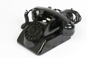
When miniature ceramic capacitors were used, this could be done
inconspicuously as part of a staged repair job, for example.
The image on the right shows the
Heemaf model 1955 telephone set
that was used at the NRP for the initial tests.
The reason for using this model for the first tests, was probably
because it was used on the local PABX at the NRP.
In this photograph
that was taken around 1961, we see the two NRP
directors Gerhard Prins and At Admiraal at work in one of their
offices. In front of them, on the desk at the right,
is a Heemaf telephone set.
|
|
|
The PABX was connected to a remote NRP-site via a 6 km long
isolated telephone line, on which the WEC was tested.
Although there was a wide variety in specifications between telephone
sets and exchanges in the various countries in the world, the
operating principle was always identical. In most countries,
only a couple of telephone sets were approved for connection to the
public exchange, and these were nearly always supplied by the state-owned
telecom monopolist (PTT). Likewise, the PABX was also supplied by the
PTT, making it easier to covertly install components.
➤ Photograph of Heemaf telephone at the NRP
|
|
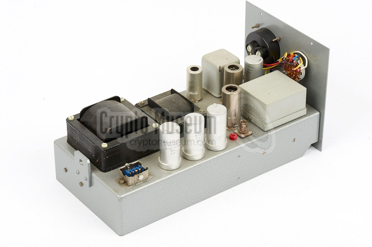
The WEC Mk I is housed in grey hamerite metal enclosure that measures
approx. 52 x 38 x 16 cm. It consists of a meetal frame in which three
modules or inserts are mounted from the front. The interior can
be accessed by removing the screws at the edges of the top panel,
after which the top panel can be removed. The three modules are interconnected
via internal cables.
|
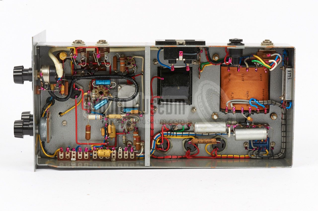
Each of the three modules can be extracted after
removing the screws around the edges of their front panel and disconnecting
the internal wiring. Below, each module will be discussed further.
The full circuit diagram of each section, complete with a technical description,
can be downloaded at the bottom of this page.
➤ Technical manual
|
|
|
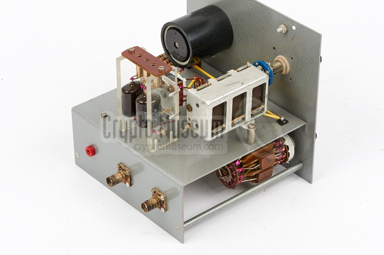
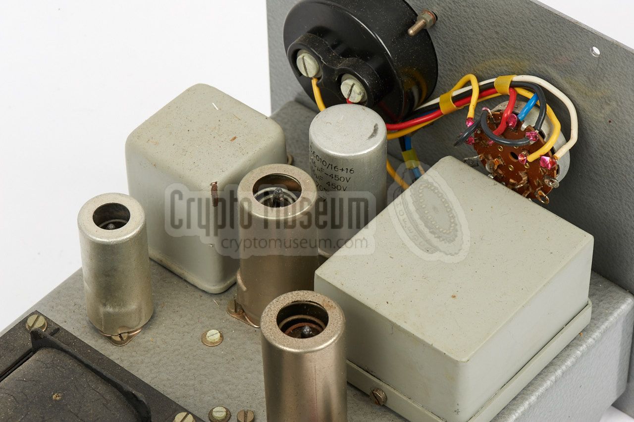
The leftmost unit is the transmitter. It consists of a Hartley type
oscillator that operates directly on the desired carrier frequency
(20-300 kHz). It is followed by a power amplifier (PA) with negative feedback,
in order to minimise distortion and noise. The transmitter also has
an Automatic Voltage Control circuit (AVC), that keeps the output (line)
voltage at a constant level.
The image on the right shows the transmitter. The large rectangular grey block
at the right is the oscillator's tuning capacitor.
|
|
|
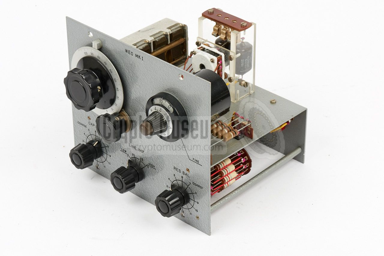
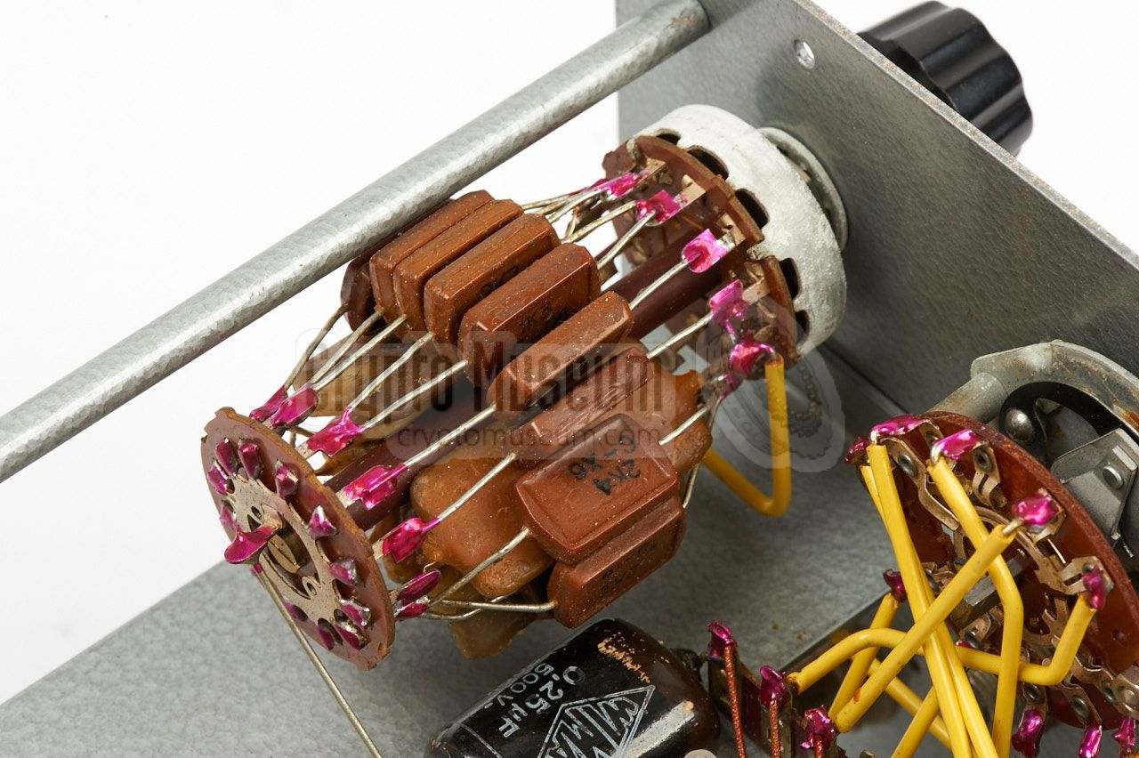
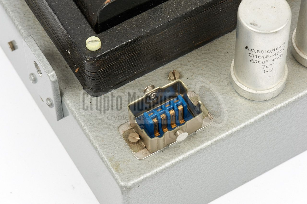
The line interface is the smallest of the three modules, and provides
a proper and balanced connection to the telephone line, to ensure the best
possible energy transfer.
The interface also acts as a duplexer, which allows transmitter
and receiver to share the same (intercepted) line,
using the same carrier frequency.
This means that the duplexer has to cancel-out most of the (strong)
transmission signal at the receiver's input, in order to avoid receiver
overloading. This is also known as spillover cancellation.
|
|
|
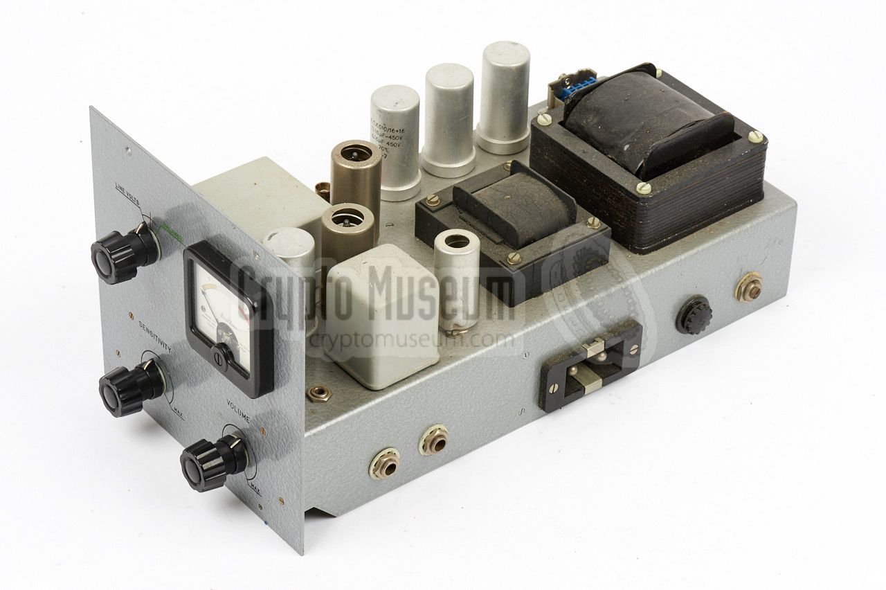
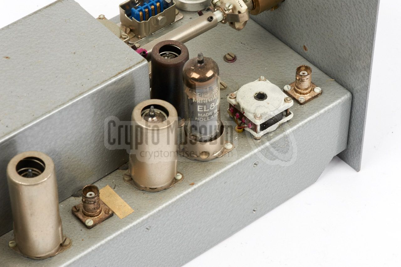
The rightmost module is the receiver, which consists of two pre-amplifiers
followed by a detector, an audio band-pass filter and several amplifier
stages with Automatic Gain Control (AGC). The meter is used to check the
carrier amplitude or the duplexer balance.
The receiver module also carries the mains Power Supply Unit (PSU).
At the lower edge of the right side, the mains socket and the mains fuse
are located. When the module is installed in the case, these connections
protrude the holes in the right side of the case.
|
|
|
In 1961, at the request of the CIA, the NRP developed a variant of the
WEC system, under the codename Rocking Chair (RC).
The principle of the RC was to connect a Passive Element (PE), similar to the
one used with Easy Chair systems, directly to the telephone line in
the target area.
At a tapping point outside the target area, a WEC unit was used to active
the PE and to receive the intercepted audio.
➤ More information
|
|
|
Device Covert listening device Medium Telephone line Frequency 20 - 300 kHz (3 bands) Mains 110 or 220V AC (switch-selectable) Size 52 x 387 x 16 cm Weight ?
|
|
CIA
|
|
Central Intelligence Agency
United Status intelligence agency.
➤ More
|
|
EC
|
|
Easy Chair
CIA codename for the super-secret project to develop covert listening devices
based on the principle of the
Russian resonant cavity microphone,
also known as The Thing.
The name EASY CHAIR is also written as EASYCHAIR.
➤ More
|
|
LP
|
|
Listening Post
Common expression for the monitoring station. In the case of a PE, this
is also the position of the activation transmitter.
|
|
NRP
|
|
Nederlands Radar Proefstation
Dutch Radar Laboratory, at the time located in Noordwijk (Netherlands).
➤ More
|
|
PE
|
|
Passive Element
NRP name for derivatives of the resonant cavity microphone.
In this context, passive means that it does not have its own local
power source.
|
|
RC
|
|
Rocking Chair
CIA code name for a project to develop a passive covert listening device
that is powered by RF energy transmitted to it via a regular analogue
telephone line, and delivering its intercepted audio via the same line.
Requires WEC equipment at the tapping point.
➤ More
|
|
WEC
|
|
Wired Easy Chair
Easy Chair bugging equipment that was designed to operate via wires.
In this case, an analogue telephone line is used to carry energy and
intelligence.
|
- NRP/CIA, Collection of documents related to WEC equipment
1960-1963. Crypto Museum Archive CM 302572 (see above).
- Anonymous, WEC Mk I Wired Easy Chair device
September 2016.
|
|
|
|
Any links shown in red are currently unavailable.
If you like the information on this website, why not make a donation?
© Crypto Museum. Created: Wednesday 04 January 2017. Last changed: Monday, 21 November 2022 - 16:28 CET.
|
 |

|
|
|


