|
|
|
|
|

|
|
CIA NRP EC ← URS-4
The image on the right shows the URT-4L with its batteries and
case shell removed. At the top it has a socket for connection of a
VHF 170 MHz Sleevex antenna, a socket for an external
marker button, an ON/OFF switch and a marker button.
The marker push-button on the front panel is connected in parallel to
the SMB socket for an external one. This was done to allow body-worn
operation during a survey. From 1982 onwards, the front panel
also held a red power LED.
The unit is typically powered by a 6V
battery pack that is connected to the
terminals at the rear.
|
|
|
The unit transmits a narrow-band 30 kHz wide signal, on a predetermined
crystal-driven spot frequency in the VHF band (either 168 or 169 or 170 MHz),
with an average output power of 160 mW (+22 dBm). It produces an on-off
keyed audio tone of 1250 Hz. When the MARK push-button is pressed, this
tone changes to 1350 Hz, to allow easy identification at the receiving end.
➤ Check out the complete URS-4 system
|
-
In a telecommunications system, the link budget is the sum of all gains
and losses from transmitter, through the medium to the receiver.
➤ Wikipedia
-
In the context of the URS-4 system, the VHF-high band (170 MHz) is known
as the low band, hence the letter 'L' in the model name. The
316 MHz band was known as the high band (H).
|
The diagram below shows the URT-4L transmitter without batteries, but with
the Sleevex antenna and the external MARK button connected at the front panel.
The unit is powered by four AA-size 1.5V batteries that should be connected
to the terminals at the rear panel. The transmitter is turned ON with the
miniature switch at the front panel, which also enables the 1250 Hz tone.
|
The 130 Hz marker tone can be activated with the push-button on the
transmitter's front panel. However, when the unit is body-worn during a
survey, it might be difficult to reach this button.
For this reason, a wired push-button was supplied with the URS-4 survey set.
It can be connected to the female SMB socket of both transmitters and is
connected in parallel to the push-button on the front panel.
|
|
|
The URS-4 set was supplied with two complete sets of Sleevex antennas
(three models each). One set was tuned for the VHF frequencies, whilst the
other set (the shorter ones) was tuned for the UHF frequencies.
Each Sleevex antenna has a colour coded ring at its base, that indicates
the environment (medium or diëlectricum) for which it has been designed.
➤ More information
|
|
|
The URT-4L was designed for operation in combination with the URR-4 receiver,
which was also supplied as part of the URS-4 survey set.
When working with the URT-4L, the low-band (VHF) plug-in had to be installed
in the URR-4 receiver and the required frequency has to be selected with the
rotary knob on the plug-in.
|
|
|
|
The URT-4L transmitter is housed in a strong brass enclosure, that was
probably painted in the same bright green colours as the receiver. It
consists of a double-sided printed circuit board (PCB) that is mounted
inside a brass frame, which in turn is enclosed by a brass case shell.
|
The case shell is longer than the transmitter itself, in order to accomodate
the batteries. The case shell is held in place by four screws located close
to the front panel (two at either side). After removing these four screws,
the transmitter can be extracted from the case shell. The image on the right
shows the extracted 'bare' transmitter.
At the left is the front panel which holds the controls and connections to
the outside world. At the right is a pertinax panel with four battery terminals.
It accepts two battery holders with two 1.5V AA-size penlight cells each
(6V total).
|
|
|
|
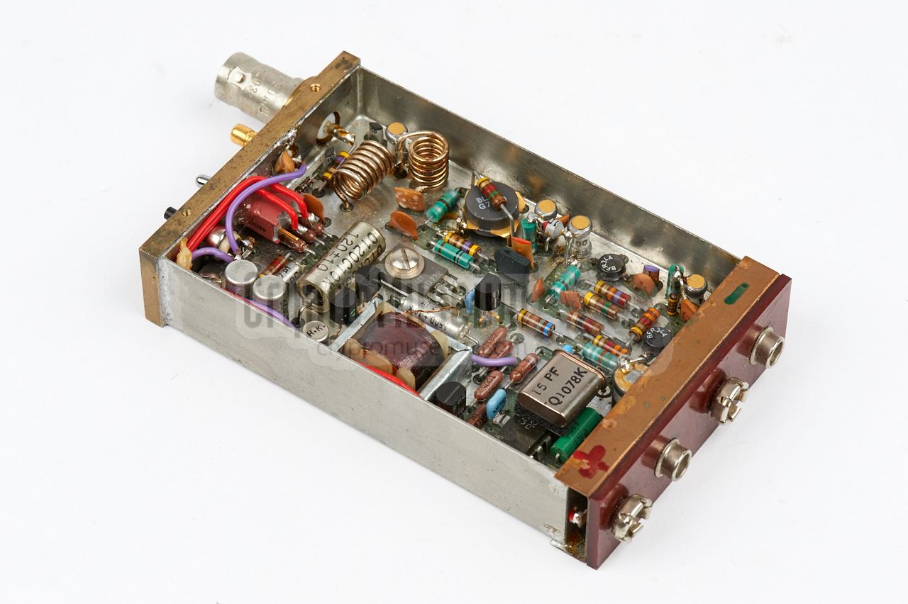
At the bottom right is the crystal that determines the output frequency.
Below the crystal is a CD4011 that delivers the 1250 Hz square-wave audio tone,
that is directly fed to the on-off modulator built around the BD228 at the
centre. Although the circuit is largely built with silicon transistors,
there are still two germanium types as the bottom left. They are part of
the power supply (protection against reverse voltage)
and are used because of their low voltage-drop.
|
The unit shown here was rediscovered in 2017 [1]. It was found without the case
shell and with some of the wiring missing (cut away). After restoration at
Crypto Museum — using the original circuit diagrams as a guide [2] — it is now
fully operational again.
|
Device Reference transmitter Part of Path Loss Survey Set URS-4 Manufactuer NRP Customer CIA Year 1978 Frequency 168 or 169 or 170 MHz ± 2 kHz Output power +22 dBm (160 mW) ± 1 dB Impedance 50 Ω Harmonic suppression > 30 dB Tone frequency 1250 Hz ± 10 Hz Mark frequency 1350 Hz ± 10 Hz Modulation on-off keying RF bandsiwdth ≤ 30 kHz Supply voltage 4.5 to 7 V (minimum 4.5 V) Current < 320 mA Battery 4 x AA-size penlight (1.5V each) Dimensions 61 x 21.5 x 171 mm Weight ~ 320 grams (without batteries) Temperature -18°C to +50°C Antenna type Sleevex Antenna socket BNC Mark socket Sub-Minax/F (SMB)
|
- Tentative Proposal for Prototype XURS-4 Equipment
NRP, 8 March 1978. CM302554/x.
- Technical Attachment to Proposal for Prototype XURS-4 Equipment
NRP, 8 June 1978. CM302554/x.
- Proposal for Prototype XURS-4 Equipment
NRP, June 1978. CM302554/x.
- Operating Manual for URS-4 Path Loss Measuring System
NRP, June 1980. CM302554/x.
- Environmental Test Report on XURR-4 Receiver
NRP, August 1980. CM302554/x.
- Environmental Test Report on XURT-4L and XURT-4H Transmitters
NRP, August 1980. CM302554/x.
- Engeneering Considerations Related to XURS-4 Protype Equipment
NRP, September 1980. CM302554/x.
- URT-4L Component Layout (technical drawing)
NRP, November 1982. CM302554/x.
- Operating Manual for URS-4 Path Loss Measuring System
NRP, January 1983. CM302554/x.
- Collection of correspondence between NRP and CIA about URR-4
NRP/CIA, 21 January 1983. CM302554/x.
- Environmental Test Report on URS-4 Path Loss Measuring System
March 1983. CM302554/x.
- Environmental Test Report on URS-4 Path Loss Measuring System
May 1991. CM302554/x.
- XY-YT Miniaturschreiber Minigor, Type RE 501, Bedienungsanleitung
Goetz, Metrawatt AG, Nürnberg (Germany). Date unknown. CM302559/A.
|
- Anonymous, Almost complete URT-4L transmitter - THANKS !
Crypto Museum, July 2017.
- NRP/CIA, Collection of documents related to URS-3
Crypto Museum Archive, CM302554 (see above).
|
|
|
|
Any links shown in red are currently unavailable.
If you like the information on this website, why not make a donation?
© Crypto Museum. Created: Thursday 10 August 2017. Last changed: Sunday, 26 May 2024 - 12:13 CET.
|
 |

|
|
|