|
|
|
|
|

|
|
← URS-3 ← Easy Chair CIA NRP
The receiver was usually connected to an SRN-55 antenna
that was also suppied by the NRP. For site surveys, it was
used in combination with an URT-3 transmitter, which operated at a fixed
spot frequency in the 1380 MHz UHF band.
The results from the survey can be read directly from the meter at the
top right of the front panel,
but can also be printed on paper,
using the supplied pen recorder,
or recorded onto magnetic (audio) tape,
on an (optional) UHER tape recorder,
allowing the data to be processed
later in the environment of the head office.
|
|
|
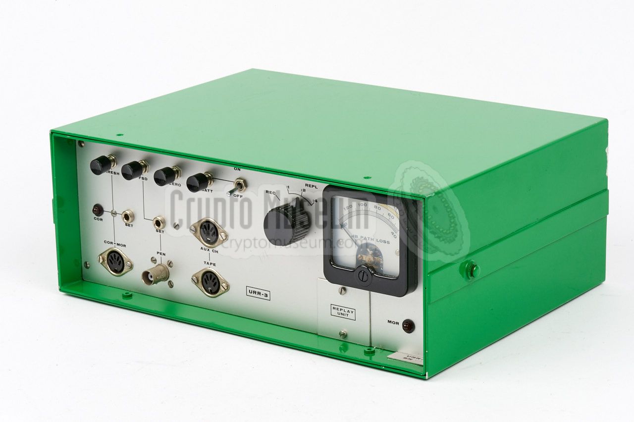
Although it was possible to play back the recorded data on the URR-3
receiver itself, this was usually done on the (optional) URR-3 Replay Unit.
The latter was a copy of the URR-3 receiver from which
the RF front-end and the IF-section were omitted. Replay units were
usually installed at the head office, allowing the survey
data to be processed more accurately. Existing Replay Units could be
converted to a full URR-3 receiver, by installing a seperately
available upgrade kit.
As we do not have a complete URR-3 receiver in our collection,
we are showing the replay unit instead. The front panel is identical,
bu the position of the RF-input socket (below the meter) is covered
by a metal panel that is labelled REPLAY UNIT. It is our intention to
eventually convert this unit into a fully operational URR-3 receiver.
Note that the URR-3 is a wideband receiver (25 MHz), whilst the very
similar URR-4 receiver is only suitable for narrowband signals (30 kHz).
|
The diagram below shows the control panel of the URR-3 Replay Unit,
which is identical to that of the URR-3 Receiver, with the exception
of the blank panel at the bottom right, marked REPLAY UNIT. On the
actual receiver this panel is replaced by the RF input socket
for the antenna.
The device has neither a built-in mains power supply unit (PSU),
nor a connection for an external one. Instead, it is powered by
a series of common 9V block batteries, installed in a removable
battery pack at the rear, identical to the one that is used
in the contemporary SRR-90 receiver.
Several years after the introduction of the URR-3, an (optional)
plug-in power supply unit (PSU) was released, that could be installed
in the bay that was normally taken by the battery pack.
|
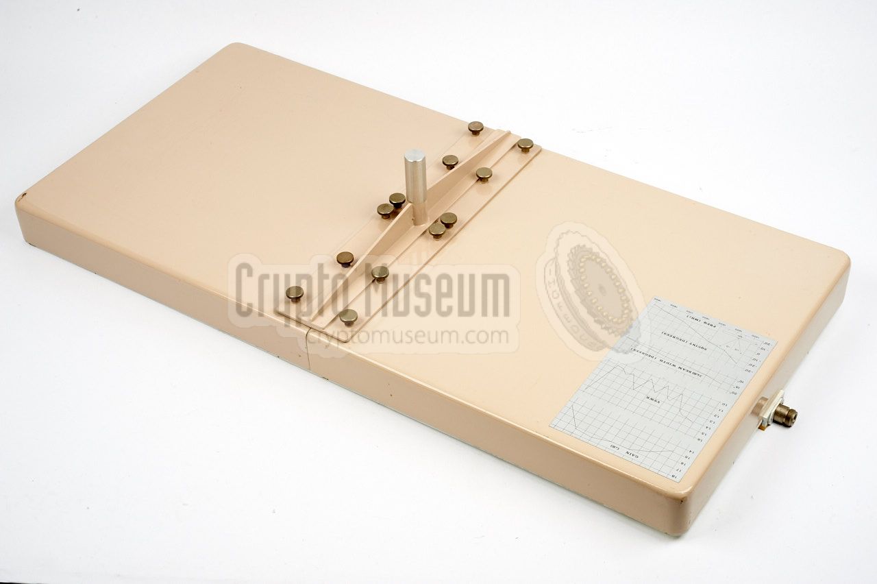
A suitable 1600 MHz directional antenna should be used with
the URR-3 receiver, such as the SRN-55 shown in the image on
the right.
Initially, this antenna was not part of the URS-3 survey set,
but from 1977 onwards, it was supplied as standard
with every URR-3 receiver.
➤ More information
|
|
|
When performing a site survey, the results of the path loss
measurements can be printed onto paper, using the Goertz
RE-501 MINOGOR pen recorder shown in the image on the right.
The device is battery powered and prints the data, relative
to time, onto a 20 cm wide thermal paper strip for later
processing.
|
|
|
In addition to printing the measurement data onto paper,
it was also possible to record it onto a magnetic (audio)
tape, using the UHER recorder shown in the image on the right.
UHER tape recorders were very popular during the 1960s and
1970s, as they were among the first affordable portable
tape recorders with professional performance.
➤ More information
|
|
|
|
The URR-3 is housed in a strong aluminium case in bright green
colours. It consists of a frame to which all parts are mounted,
enclosed by a green case shell. After removing a single screw from the
rear side, the case shell can be removed, exposing the interior,
as shown in the image below.
|
Looking at the receiver from the rear, there are three plug-in
cards that can be removed from the side. These cards hold the
Filter board, the VFV converter board and the LOG & DC board.
The space between the plug-in cards and the front panel is
normally taken by the RF front-end. It is empty here, as the
device shown here is the Replay Unit. At the right are two bays.
The large one is for the battery pack,
whilst the small one at the bottom takes the
60 MHz IF-unit.
|
|
|
|
More information will be added as and when it becomes available.
|
- Mic out
- Ground
- Mic in
- Tone out
- Tone in
|
|
- Mic in
- Ground
- Mic out
- Mic in (shorted to 1)
- Mic out
|
|
- MOR relay contact (with 4)
- Ground
- COR relay contact (with 5)
- MOR relay contact (with 1)
- COR relay contact (with 3)
|
|
Frequency 1000 - 1600 MHz IF frequency 60 MHz Bandwidth 25 MHz Subcarrier 20 kHz Path loss indication quasi logarithmic SC bandwidth 10 kHz Indicating ranges 30-100 and 60-130 dB Demodulation Compatible with URT-3 Audio out 1 mW into 600 Ω Temperature 0°C to +60°C Power supply Internal, 4 x 9V block battery
|
- Engineering Report for XURS-3
NRP, August 1974. CM302516/A.
- Collection of notes, correspondence and circuit diagrams related to URS-3
NRP, December 1975 - November 1976. CM302516/B.
- Manual for URS-3
NRP, November 1976. CM302516/C.
- Manual for URS-3
NRP, December 1976. CM302516/D.
- Proposal for Production of URS-3 Systems
NRP, March 1977. CM302516/E.
|
- NRP/CIA, Collection of documents related to URS-3
Crypto Museum Archive, CM302516 (see above).
|
|
|
|
Any links shown in red are currently unavailable.
If you like the information on this website, why not make a donation?
© Crypto Museum. Created: Thursday 10 August 2017. Last changed: Sunday, 13 August 2017 - 16:29 CET.
|
 |

|
|
|