|
|
|
|
|

|
|
Stasi 31218 → ← 31216
The 31217 belongs to the 3rd generation of DDR radio bugs and is based
on the 31216.
Unlike the 31216 however, it does not have a built-in
microphone and battery, but instead features an audio amplifier
that makes it more sensitive
and allows the application of a dynamic microphone.
The device delivers an output power of 15 to 40 mW – subject to the applied
voltage – which was sufficient for
a range of 150 metres under typical urban circumstances. It has an 11 cm
long wire antenna that should be straightened and free from obstacles for
the best transmission range.
|
|
|
The transmitter can be powered by any DC voltage between 1.5 and 9V, but was
typically used in the 6V - 9V range, as that produces more RF output power and
increases the range. A miniature 31217-20 mains power supply unit (PSU)
was available for transmitters that had to be powered for an extended period
of time. As the transmitter is based on a free-running RF oscillator, it is
rather unstable. The frequency depends on the room temperature, applied voltage,
obstacles in its vicinity and people moving around in the bugged room.
For this reason, the complementary
31215
and 31225
receivers had a very wide Automatic Frequency Control (AFC) tracking range.
The device was part of a family – consisting of the
31216,
31217
and 31218 –
and was available in several variants, allowing
it to be used with a variety of microphones and audio-masking 2 units.
It was mainly used in combination with microphones from Western manufacturers
such as Sennheiser and
Knowles 3 ,
commonly obtained under the pretence of hearing aid manufacturing.
|
 |
-
Institut für Technische Untersuchungen (ITU) was a covert operation
of the OTS, the Operativ-technische Sektor (Technical Operations
Sector) of the MfS (Stasi).
Not to be confused with the CIA's OTS.
-
In Stasi terminology, audio masking
was known as Sprachverschleierung (speech concealment), or SV.
-
Note that Knowles
was an American manufacturer that supplied
miniature microphones
for hearing aids. Ironically, many of their microphones were
developed with funding from the US
Central Intelligence Agency (CIA)
for use with CIA bugs.
|
The diagrams below show different setups with several variants of the
31217 at the left. The transmitter is powered by a 9V DC source, either
from a battery or a miniature 31217-20 power supply unit (PSU).
The basic setup, with a dynamic microphone, is configured as show below.
This is the configuration featured on this page in combination
with a Knowles dynamic microphone.
|
| |
Basic 31217-1 setup with dynamic microphone
|
Variant 31217-111 was very similar to the basic 31217-1 unit, but was
suitable for connection of an electret microphone, which greatly improves
the audio sensitivity of the unit. In most cases it was used with a
minature Knowles BT1751 electret microphone.
These units are usually powered by 6 to 9V, whilst an extra wire connection
provides the 1.5V to power the electret microphone.
|
| |
Setup 31217-111 with electret microphone
|
Although the 31217 works at a relatively high frequency (940 - 980 MHz)
it is easily possible to pick up and monitor the signal – either accidentally
or deliberately – by means of a suitable FM receiver. In order to avoid
eavesdropping of the signal, it could be enhanced with an
optional audio-masking
unit, in German known as SVM or Sprachverschleierung 1 (speech
concealment).
The SVM-unit modulates the audio signal onto a carrier that is
well above the human-audible range. In addition it injects a 40 or 100 Hz
hum into the audio baseband in order to confuse the eavesdropper.
This technique is also known as
subcarrier audio masking
or double FM (FM/FM).
|
| |
Setup 31217-100 with subcarrier audio masking unit (FM/FM)
|
Although most radio bugs were battery powered, this limits the unit's
operational life, as batteries have a finite capacity. For units that had
to be operational for an extended period of time – or even permanently –
the miniature 31217-20 mains power adapter was available.
|
| |
Setup with 31217-20 mains power supply unit (PSU)
|
At the right is a special 31215
or a 31225 receiver, which is suitable for the 940
- 980 MHz frequency range, and has an AFC with a very wide tracking range,
so that it can follow the (instable) free-running transmitter. The transmission
frequency is subject to distance to objects, motion of objects or people
in the vicinity of the transmitter, temperature and battery voltage.
|
|
-
In the abbreviation SVM, the letters SV stand for Sprachverschleierung
(speech concealment) by means of subcarrier modulation (double FM),
whilst M means Maskerator (masking), referring to the injected
hum.
|
The diagram below shows how the
project number
is constructed.
The first digit tells us which department was responsible for it. In this
case it is department 33, which was Außenstelle Beucha (Outstation
Beucha). Before 1977, the prefix '3' was omitted, or the prefix 'AB' was used.
The next two digits define the theme and the group within
the theme. The next two digits define the actual project (within the group).
If a device is part of a kit, the number behind the dash specifies the item
number (within the kit). The last two digits are optional, and
specify the version or variant.
|
|
|
Known versions and options
|
|
|
-
These versions contain different hardware (i.e. a different transmitter).
|
|
Rainer Eppelmann was a reverend in East-Germany, who voiced strong
crititism against the DDR's communist regime [4]. In December 1988 he found a
31217 bug hidden behind a defective wall socket in his office. A month later,
on 26 and 28 January 1989, he found another two in his living room –
with help of Stasi informant 1 Rainer Dietrich – one of which was hidden
inside his radio.
|
In December '88, the West German
Verfassungsschutz (BfV) 2
had provided Ulrich Schwarz – a correspondent of Der Spiegel –
with a device for
finding bugs.
Schwarz gave it to Eppelmann, who used it for finding the bug
shown in the image on the right behind a defective wall socket [5].
At the bottom is the 31217-111 bug (1)
with its protective PVC cover and the top lid removed.
According to the label, it has serial number 14.
At the left is a Knowles BT1751 microphone
(2) covered in a black shrink sleeve. It is sensitive enough to pick up
any sound in the room.
|
|
|
|
At the top is the miniature transformerless mains
power supply unit (PSU) (3) which is a variant of the 31217-20,
also shown with its cover removed.
At the top left are the remains of the plaster (4) behind which
the bug was hidden.
The bug was permanently powered and had therefore an unlimited lifespan,
providing the Stasi with first-rate intelligence about every discussion
that had taken place in the room. Because of its high frequency
(940 - 980 MHz), it did not cause interference with regular radio
or television broadcasts and was therefore very difficult to discover.
|
A month later – being suspicious of further bugs – Eppelmann called in
the help of Rainer Dietrich, who was a member of the Initiative Frieden
und Menschenrechte (IFM) 3
but also an unofficial Stasi employee (IM) 1 with the codename Cindy.
Dietrich clearly put himself a risk by
helping Eppelmann to find covert listening devices that were
placed there at the authority of the Stasi.
On 26 and 28 January 1989, Dietrich carried out a covert survey of Eppelmann's
living room and discovers two further bugs: one hidden inside the radio,
and another one hidden inside a lamp.
|
|
|
The latter is shown in the image above, with Dietrich (wearing gloves)
holding the discovered bug in his hands.
Also present at the survey, was photographer Bernd Weu who took the
picture shown above. Being a member of Eppelmann's church, he
has been documenting the curch's work. In February 2018, Weu transferred
most of his work to the Havemann Foundation [4].
➤ Read the full story (off-site)
|
-
In Stasi terminology an informant is known as an
Inoffizielle Mitarbeiter (unofficial eployee), commonly
abbreviated to IM and often nicknamed: die Spitzel
(the informants).
➤ More
-
Verfassungsschutz is the German word for Protection of the Constitution.
➤ More
-
Initiative for Peace and Human Rights. ➤ Wikipedia
|
A good example of a practical implementation of the 31217 is the
so-called Stopfen, which used a Knowles electret microphone
that was hidden inside a wooden plug.
It was usually mounted mounted inside the bottom or the top of
the central access door to, say, a hotel room.
➤ More information
|
|
|
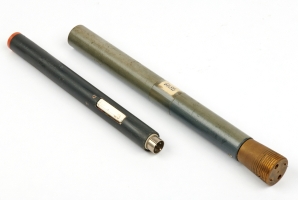
Another example of a 31217-1 that was used for a special application is the
Holzwurm bug (woodworm) shown in the image on the right.
The device consists of two concentric plastic pipes that hold the batteries
and the transmitter, plus a brass section at the bottom – holding a
sensitive microphone –
that can be screwed into a door frame.
At the bottom are two sharp nails that allow it
to be covered by a wooden disc, so that it looks like a wooden dowel.
➤ More information
|
|
|
|
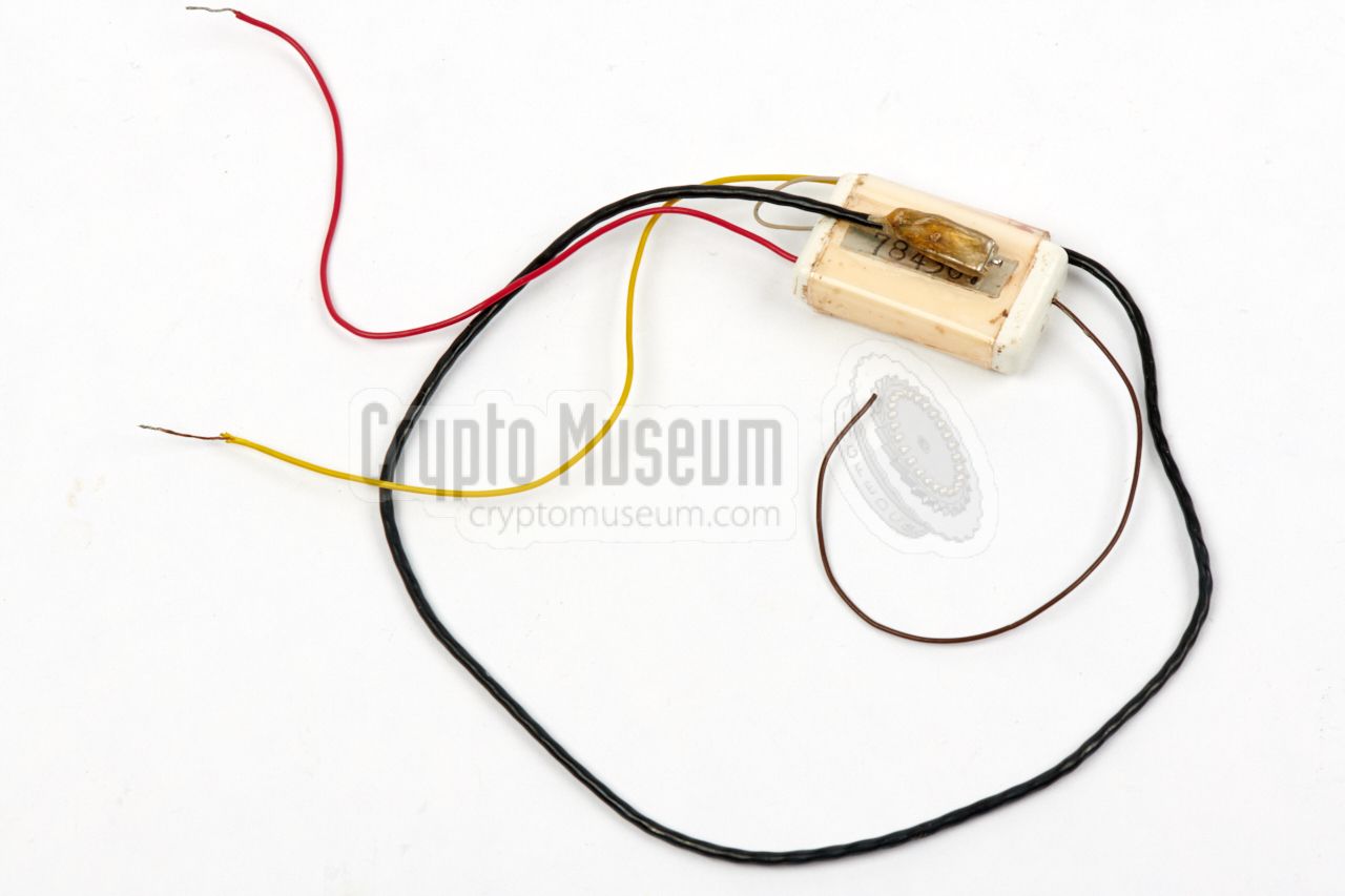
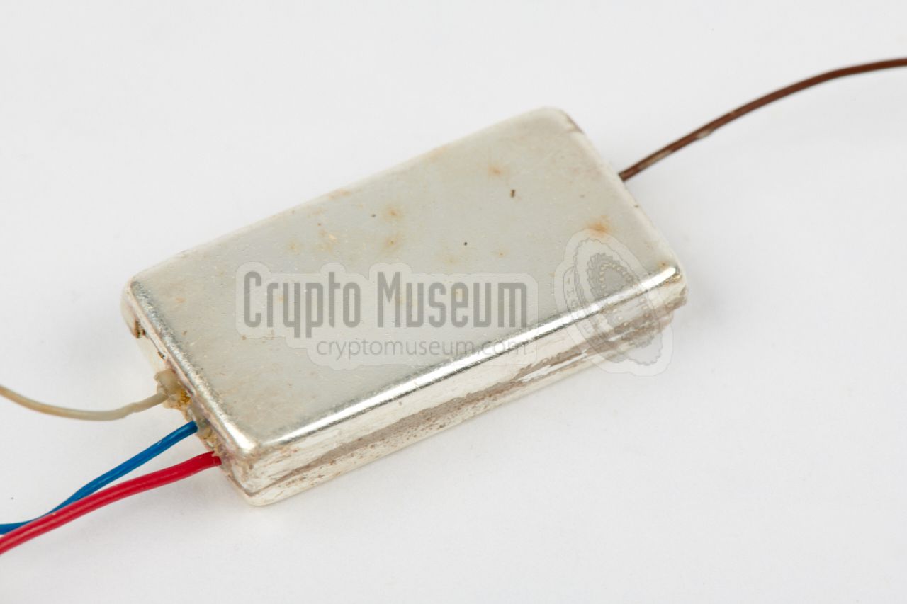
The 31217-1 bug is housed inside a protective case or sleeve, which
consists of two thin PVC case shells, with cut-outs for the wires at both
of the short sides. The case shells, and in some cases part of the wiring,
are held together
by means of cellotape.
Inside is a silver-plated can.
|
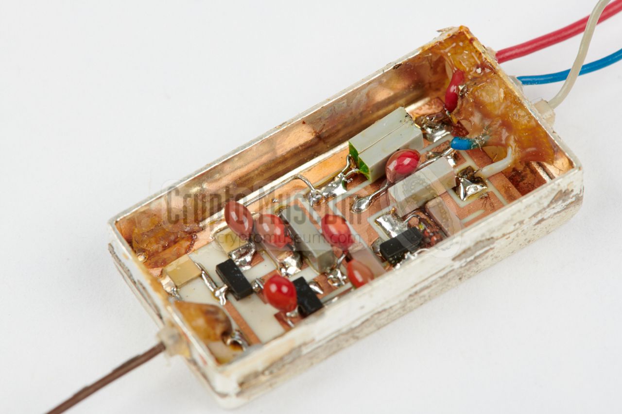
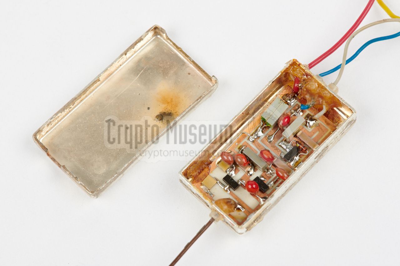
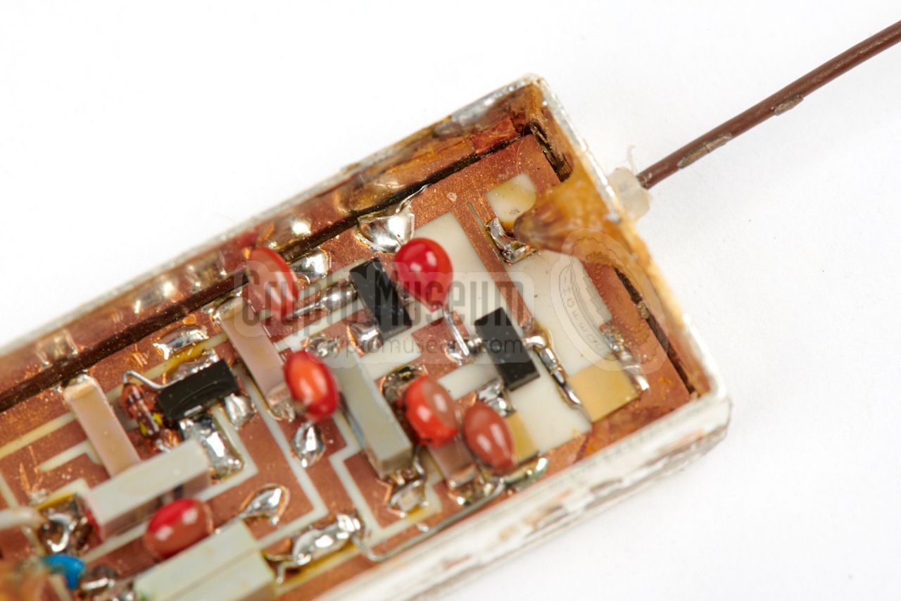
After cutting through the cellotape, the two
case shells can be removed
and the silver-plated copper can is exposed. The can is close with a
removable cap that is usually soldered in place.
The image on the right shows the enclosure of the 31217-1 after the cap
has been removed from the can. Inside the can is a
small ceramic PCB,
roughly twice the size of the one
inside the 31216-1,
with miniature components.
The RF section
(at the side of the brown wire) is nearly identical to the
entire 31216 unit. The remaining space is taken by a 2-stage audio pre-amplifier.
|
|
|
|
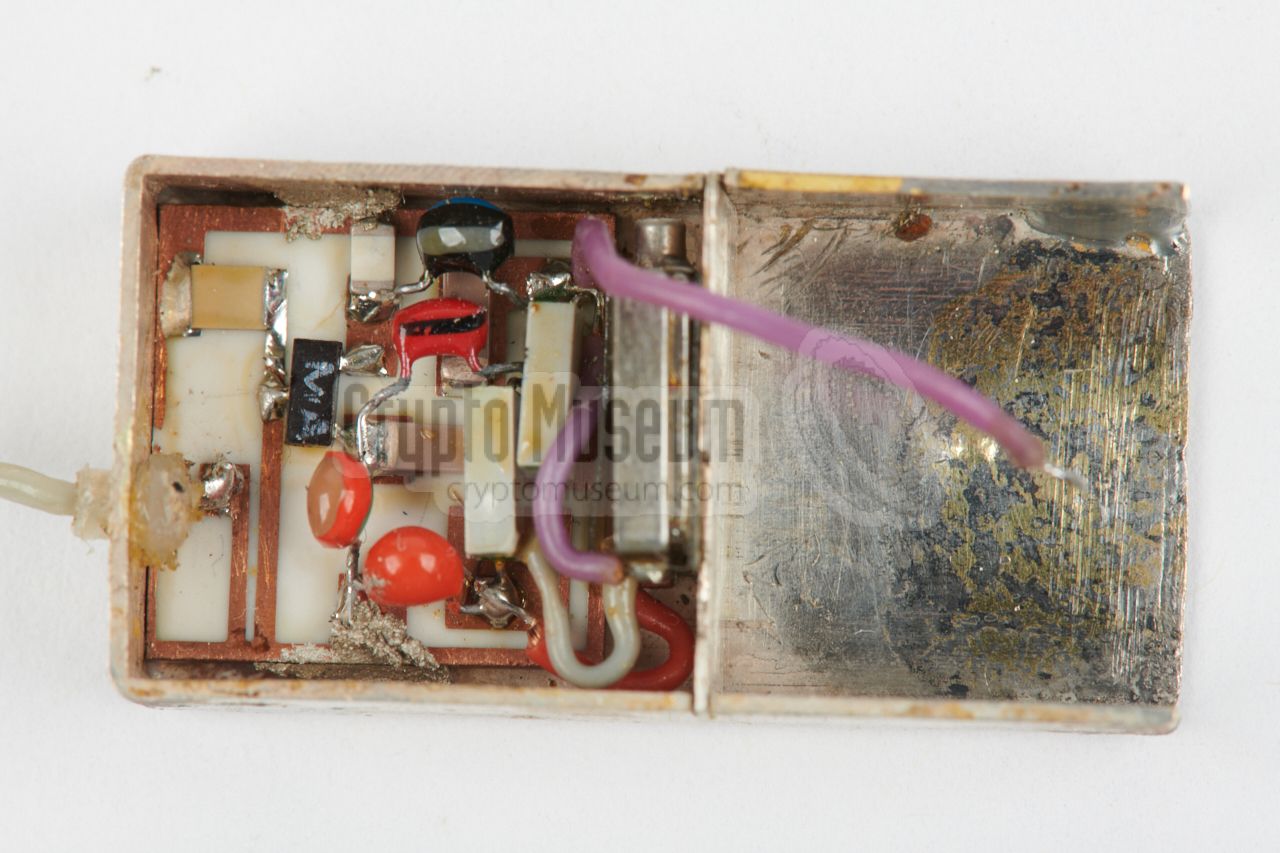
Microphone and power should be connected to the three wires at the other
side of the case. Note that the 31217-111 variant has 4 wires at that side,
as it has to provide the power necessary for the electret microphone.
The circuit is actually a hybrid of regular (conventional) components and
surface mount parts (SMD), with the latter usually being obtained from
Western manufacturers.
|
Below is the circuit diagram of the basic 31217-1 transmitter. The actual
RF-stage is built around a single BFS17 transistor and is nearly itentical
to the 31216-1 bug. At the top right is a stripline
transformer (TR) to which the antenna is coupled inductively. The exact
frequency (in the the 940 - 980 MHz range) is determined by the position of
the 4.7 pF capacitor that is connected between the longest stripline
and ground. Note that the frequency strongly depends on the power voltage.
Instead of connecting the microphone directly at the
base of the BFS17, like with the 31216-1,
the 31217-1 has a 2-stage amplifier, built around two BCW60 transistors
(T1, T2). This variant is suitable for connection of a dynamic
microphone, which is connected between LF (3)
and 0V (2).
The 31217-111 variant is nearly identical to the 31217-1, but is suitable for
use with an electret microphone. The power for the electret is provided by an
extra voltage divider (8k2, 1k8) and is available from the Vm terminal
(4)
at the left. It was commonly used with a
Knowles microphone.
|
|
Due to the fact that the transmitter is built around a single-transistor
free-running RF oscillator, the transmission frequency is not stable
and greatly suffers from the so-called hand-effect. 1 Furthermore,
the frequency varies with the room temperature and with the applied power
voltage. The 31217-1 accepts a power input range of 1.5 to 9V DC, but was
typically used in the 6V — 9V range, as it produces more RF output power.
Between 6V and 9V, the frequency varies ~ 4 MHz.
|
|
The maximimum distance between the 31217 and a surveillance
receiver, known as the range, greatly depends on the applied power
voltage and, hence, the RF output power produced by the unit (15 to 40 mW).
Furthermore, its 11 cm wire antenna had to be straight and free from any
obstacles. In a urban environment, powered at 9V, the device had a range of ~ 150 metres.
|
-
Moving the hand close to the device, affects the tuned circuit somewhat,
as a result of which the transmission frequency changes.
|
GND red +V (GND) 0V blue 0V Input grey Audio ANT brown Antenna
|
|
GND red +1.5 to +9V 0V blue 0V (GND for electret) Input grey Audio (from electret) Vm orange +V for electret ANT brown Antenna
|
|
Device RF covert listening device (bug) Purpose Room overhearing Model 31217 Developer Institut für Technische Untersuchungen (ITU), Außenstelle Beucha User Stasi (MfS) Frequency 940 - 980 MHz (fixed spot frequency in band V) Output 15 — 40 mW (depending on version) Antenna Wire, 11 cm (¼λ) Audio 20 Hz - 8 kHz Sensitivity Class III (1.7 ±0.3 µbar) Deviation ± 75 kHz Modulation FM (F3) Subcarrier 22 or 24 kHz, with 80 or 100 Hz hum 1 Power 1.4 — 9V DC Dimensions 32 x 16.5 x 7 mm Weight 24 grams
|
-
Only for units with audio masking option (SVM).
|
- 1217-1 Kennblatt 1
31217-1 Datasheet (German). MfS, 13 October 1976. 8 pages.
- Technologische Vorschrift fur Gerat 1217-1 1
Manufacturing instructions (German).
MfS, 13 October 1976. 4 pages.
- Prüf- und Abgleichvorschrift fur die Gerate 1217-1 1
Test and alignment protocol for the 31217-1 (German).
MfS, 22 October 1976. 7 pages.
- Technische Unterlagen Gerät 31217-1 and 31217-2 1
Full technical documentation for device 31217-1 and 31216-2 (German).
MfS, July 1976 — October 1977. 20 pages.
- 31217-111 Kennblatt 1
31217-111 Datasheet (German). MfS, 9 August 1982. 7 pages.
- Prüf- und Abgleichvorschrift fur die Gerate 31217-111 1
Test and alignment protocol for the 31217-111 (German).
MfS, 9 August 1982. 6 pages.
- Technologische Vorschrift fur Gerat 31217-111 1
Manufacturing instructions (German).
MfS, 9 August 1982. 4 pages.
- Technische Unterlagen Gerät 31217-111 1
Full technical documentation for device 31217-111 (German)).
1976—1982. 10 pages.
- Kennblatt 31217-112 1
Concealment in a power distribution box. Datasheet (German).
MfS, Abeilung 26-4. 5 April 1984. 2 pages
- Information 2/79 Linie B 1
Battery duration of 31216-1, 31217-1, 31217-131/132/133, NTD, 31218-1.
1979, 6 pages.
- Information 3/79 Linie B 1
Connecting an electret microphone to the 31217 or 31218 9V transmitter (German).
1979. 1 page.
- Information 4/87 Aufgabe B 1
Using 31217 with a 33014 interface and 31028-12 power supply (German).
22 May 1987, 1 page.
- Hinweise fur die Erprobung der Technik 31216, 31217, 31218 1
Recommendations for application of 31216, 31217 and 31218 (German).
MfS, BV Gera OTS 0102. 8 September 1976.
|
|
-
Document obtained from BStU [2] and kindly provided
by Detlev Vreisleben [1].
|
|
-
Full name: Bundesbeauftragte für die Unterlagen des Staatssicherheitsdienstes
der ehemaligen Deutschen Demokratischen Republik
(DDR) —
Federal Commissioner for the Records of the
State Security Service
of the former German Democratic Republic (GDR) —
officially abbreviated BStU.
Since June 2021 part of the Bundesarchiv and known as
Stasi-Unterlagen-Archiv.
|
|
|
|
Any links shown in red are currently unavailable.
If you like the information on this website, why not make a donation?
© Crypto Museum. Created: Saturday 04 August 2018. Last changed: Thursday, 06 November 2025 - 15:02 CET.
|
|

|
|
|


![31217-11 bug discovered by Eppelmann in December 1988. Photograph copyright Havemann Foundation [4].](img/eppelmann_1.jpg)
![Bug discovered by Dietrich in January 1989. Photograph copyright Havemann Foundation [4].](img/eppelmann_2_large.jpg)


