|
|
|
|
|

|
High-speed morse burst encoder
The Speicher was a fully electronic burst encoder
that could send numbers in morse code a very
high speed. It was developed around 1974 in Germany.
Speicher was developed for the SP-20
and replaced earlier mechanical burst encoders, such as the NATO-issued
RT-3
and the American GRA-71.
In the Netherlands, it was also used in combination with the earlier
FSS-7 spy radio set.
|
Speicher is the German word for Memory, which perfectly
describes its function. The unit is housed in a grey case that is similar
to the cases of the SP-20 spy radio set.
It is powered by an internal battery that can be recharged
by a built-in power supply unit directly from the AC mains.
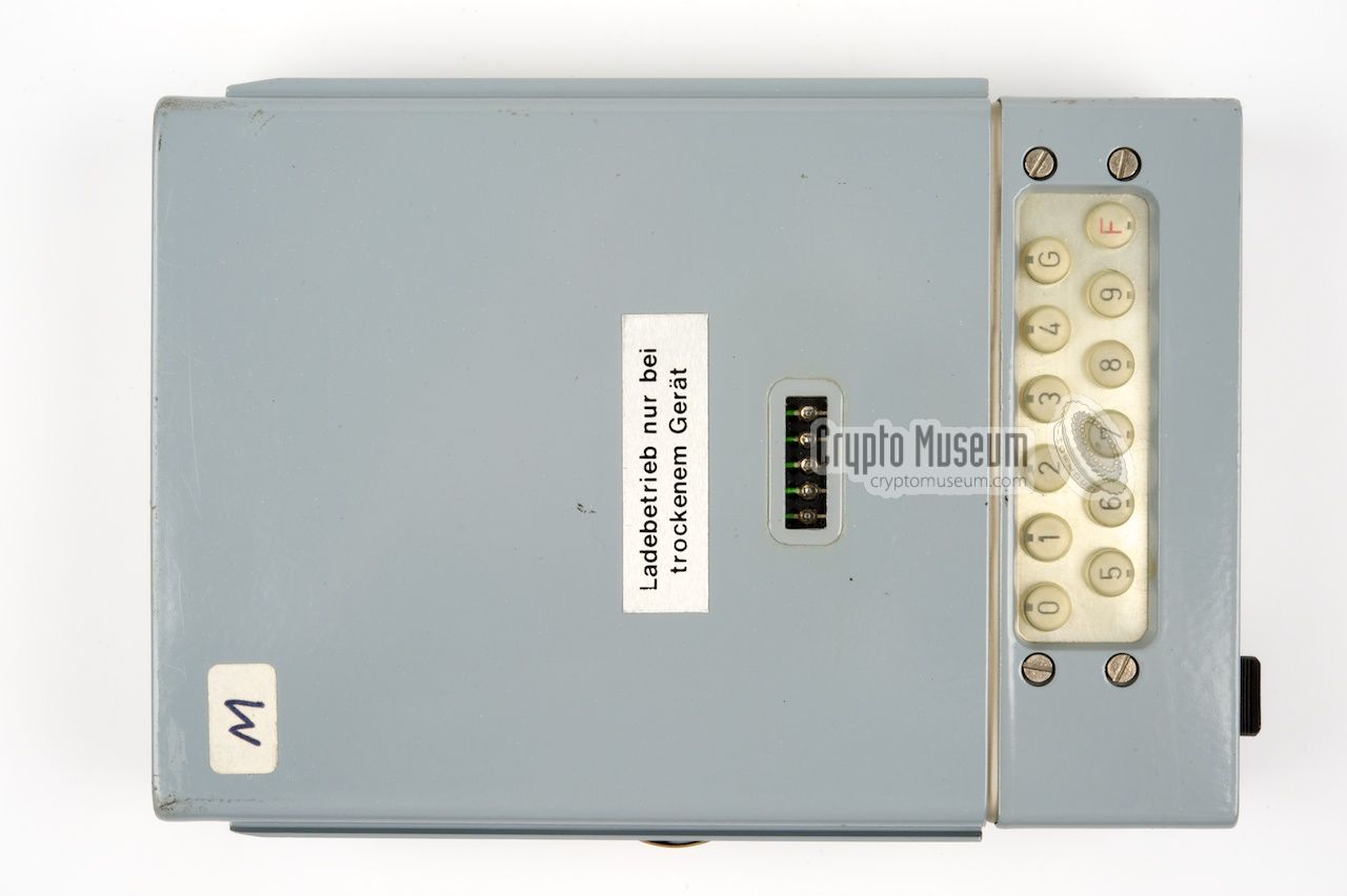
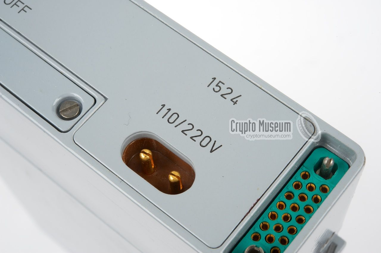
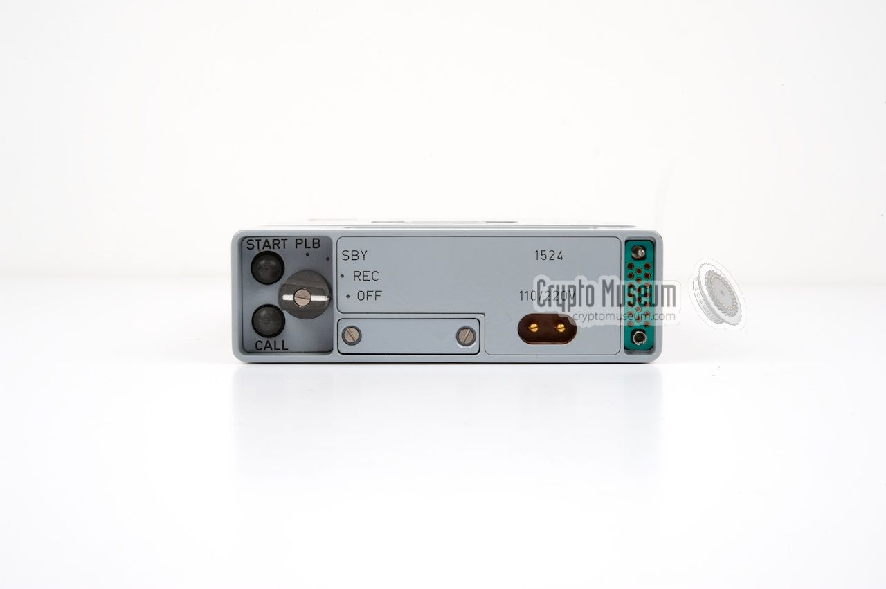
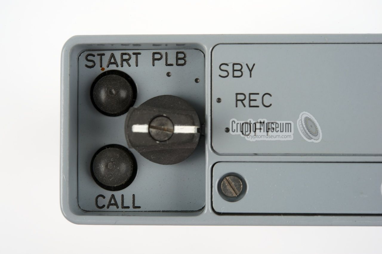
At the right of the front panel are the
sockets for the transmitter (key output) and for the 110V or 220V AC mains.
At the left is a recessed MODE selector and two push buttons,
marked START and CALL. The MODE selector has four positions:
OFF, REC, SBY (standby) and PLB (play-back).
|
|
|
It is likely that Speicher was developed exclusively for the
German Stay-Behind organisations
The Speicher was probably developed only for the (grey) stay-behind
version of the SP-20 and was to be used instead of the earlier mechanical
RT-3 burst encoder. It has not been found with the
(green) military version of the SP-20. Evidence of the use of Speicher
in combination with the SP-15 spy set was
found in The Netherlands, where it turned up in the only known surviving
SP-15 Stay-Behind container.
This container is now in the collection of Museum Jan Corver [1].
In the early 1980s, Speicher was replaced by the more versatile
MMP burst encoder, which was capable of sending both
letters and numbers in morse code at a variety of speeds, ranging
from 15 baud to an impressive 1200 baud. Some Speicher encoders
remained in service however.
At present, the manufacturer of Speicher is unknown, but given the
extremely good built quality, it is likely that it was a
high-end electronics manufacturer like H. Pfitzner or
AEG Telefunken.
|
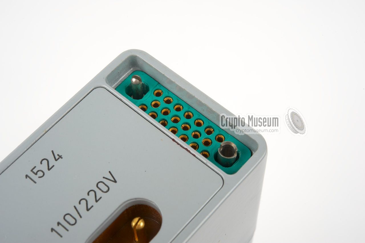
All controls and connections of the Speicher are at the front of the unit.
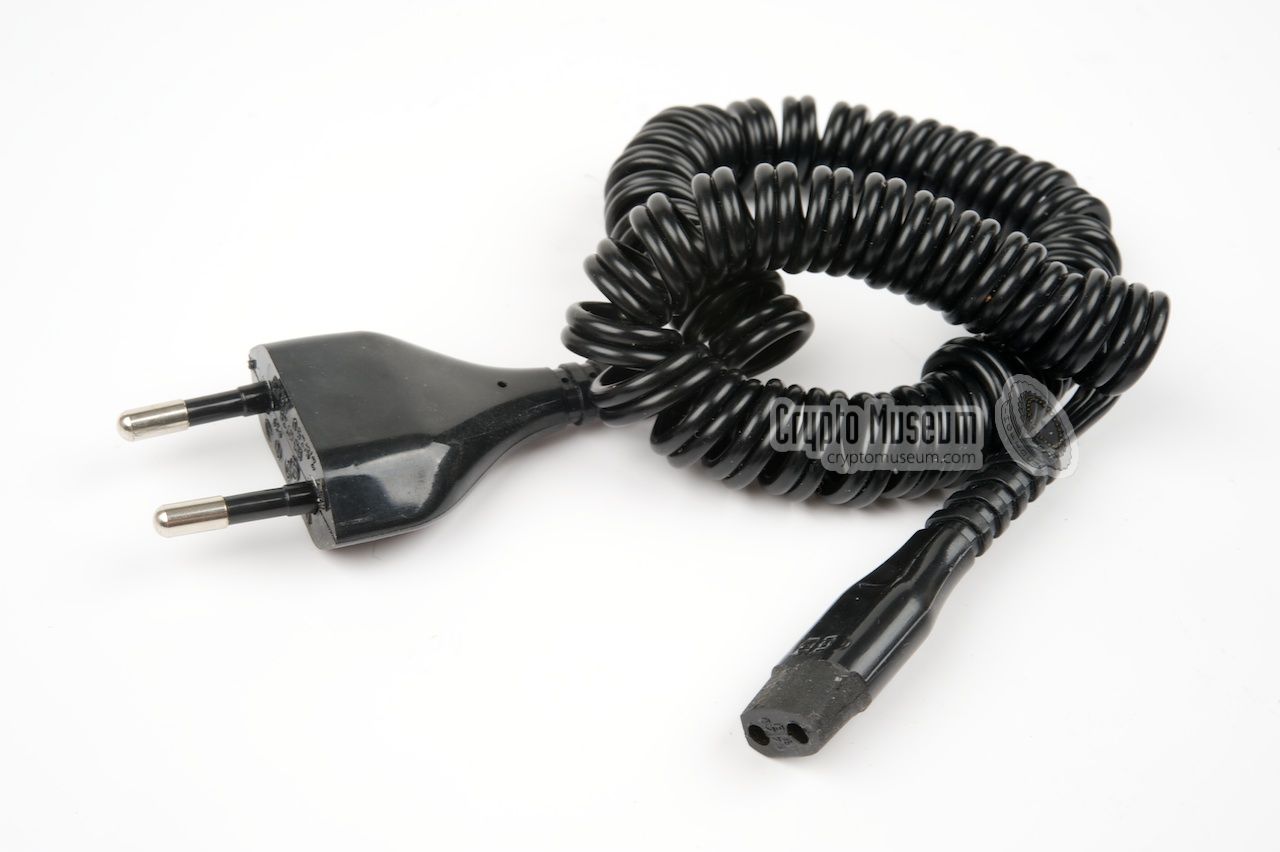
The 110-220V AC mains is connected to the small 2-pin socket at the front
right. As this socket is smaller than a common 2-pin socket (e.g. the ones
that are used on domestic equipment), a standard cable with a modified connector
is supplied. The transmitter is connected to the green socket at the right.
At the top is a small recessed keypad
with 12 buttons. Ten of these
are for the numbers (0-9) and the two remaining ones are marked
G and F. Just above the keypad is a small window with five red LEDs
that are used for counting the number of characters in a five-letter group.
The device is operated with the MODE selector at the left, in combination
with the START button. When set to REC, a message can be entered on the
numeric keypad at the top. This is fully explained below. Speicher has a
built-in 6V rechargeable battery (same type as used in the FE-8 receiver)
that is charged when the unit is connected to the mains. In SBY mode (standby),
this battery is used to retain the message. Setting the MODE selector to OFF,
clears the memory.
|
Speicher was intially developed for use in combination
with the German SP-20
spy radio set that was introduced around 1974.
For that reason it is housed in a similar case.
It is likely that it was only used with the grey version of the SP-20,
which was used for stay-behind
and clandestine operations (espionage).
➤ More information
|
|
|
When preparing a transmission, the text first has to be translated
into numbers, as the Speicher is not capable of sending letters.
The MODE selector is then placed in the record position (REC) and
the START button is pressed to place the memory counter at the beginning
(initialize).
The numbers are then entered in groups of five that are separated by
a Group Space by pressing the (G) button. The five LEDs behind
the window on top of the unit are used to count the number of characters
in a group. When all five LEDs are lit, the G-button has to be pressed.
This inserts a pause and clears the LEDs.
Once the message is complete, the F-button is pressed (Finish).
The MODE selector should now be placed in standby mode (SBY).
In this mode the message is retained in memory by the internal battery
(or the PSU when the unit is connected to the mains).
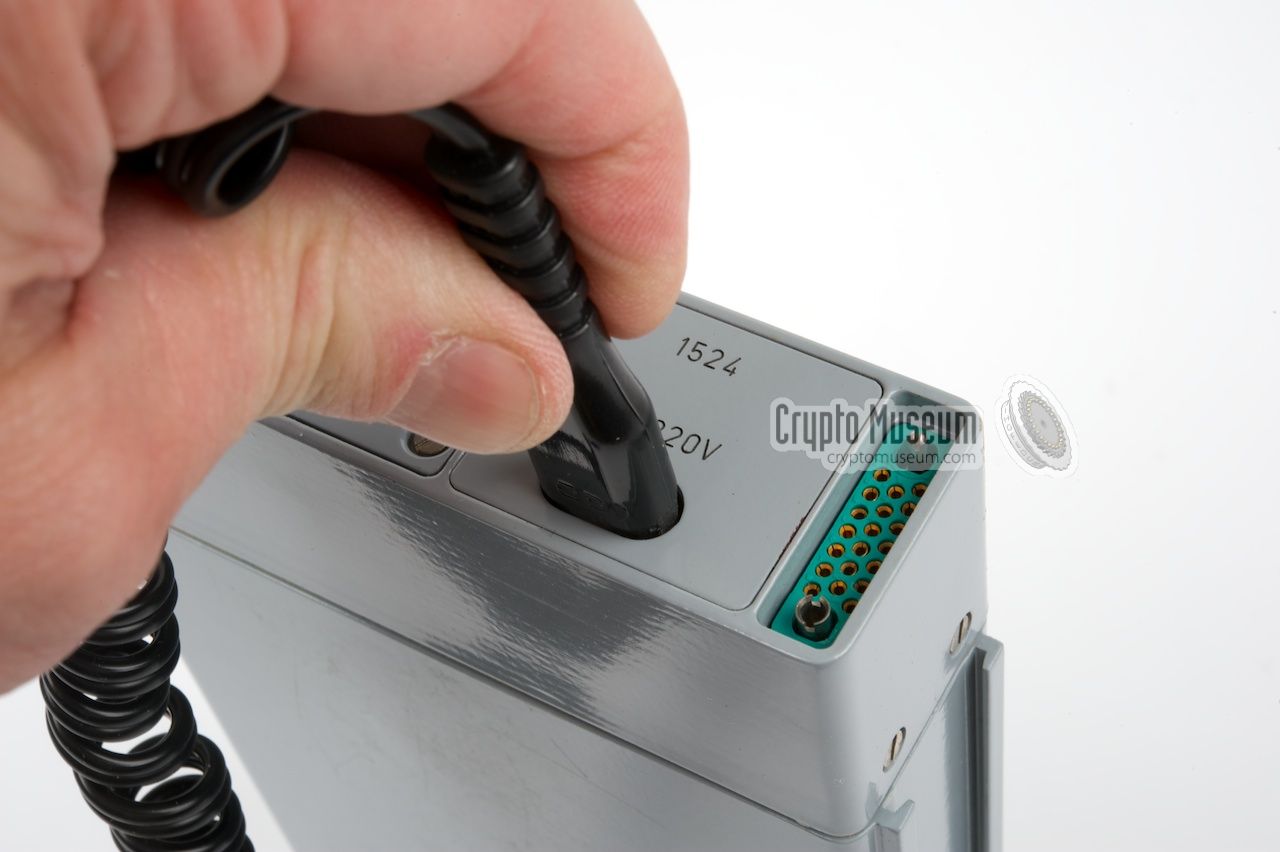
Next, connect Speicher to the transmitter, using the
special cable that is inserted into the green
socket at the front right. The cable shown here was issued especially for the
SP-15 spy radio set. Now set the MODE selector
to play-back (PLB) and press the START button. This places the memory counter
to the beginning of the message and will automatically start the transmission.
Now use the side tone output of the transmitter to monitor the
transmission. Once the burst transmission has finished, turn off
the transmitter and set the MODE selector to OFF. This clears the memory,
even when the PSU is connected or the battery is installed.
|
|
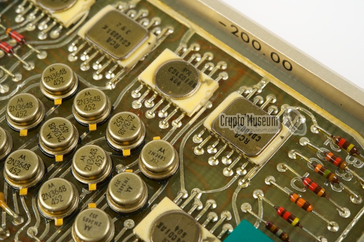
Speicher is housed in a grey painted metal enclosure with the same form factor
as the units of the SP-20 spy radio set.
It is extremely well-built and contains components that were not commonly
available in the mid-1970s. The unit consists of two parts:
the front panel with the controls and connections,
and the rear part that contains the
electronic circuits and the
power supply (PSU).
|
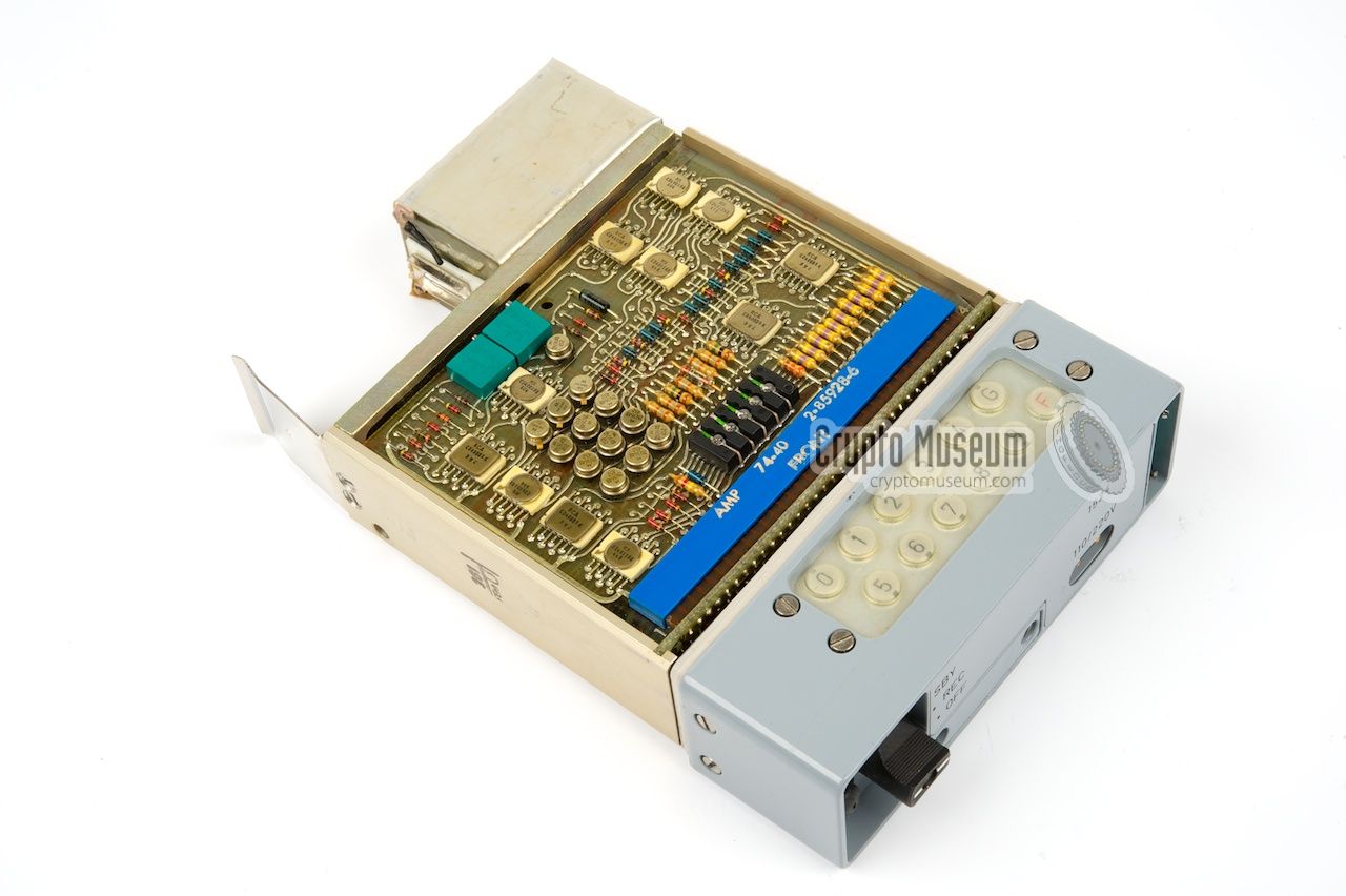
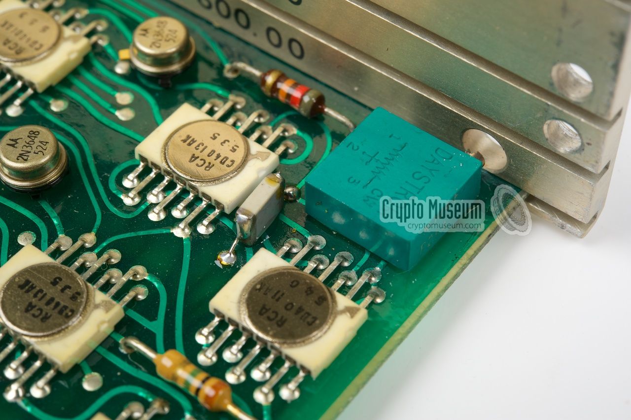
The electronics can be accessed by removing the shell from the rear section,
simply by removing a single screw at the bottom of the unit. The shell can
the be pulled towards the rear, after which the uper PCB is exposed, as shown
in the image on the right. At the rear end (at the left in the picture)
is the small PSU
and a bay for a 6V re-chargeable battery
(which is not present here).
The electronics consists of four PCBs that are connected through a backplane
behind the front panel. The PCBs are held in place by a metal frame
that is accessible from the PSU end.
|
|
|
After removing two screws at the side of the frame, the hinged rear section
with the PSU can be opened like a door,
giving access to the 4 PCBs.
Each of the PCBs can now be removed by
pulling it towards the rear,
but precautions have to be taken to avoid damage by static discharge.
|
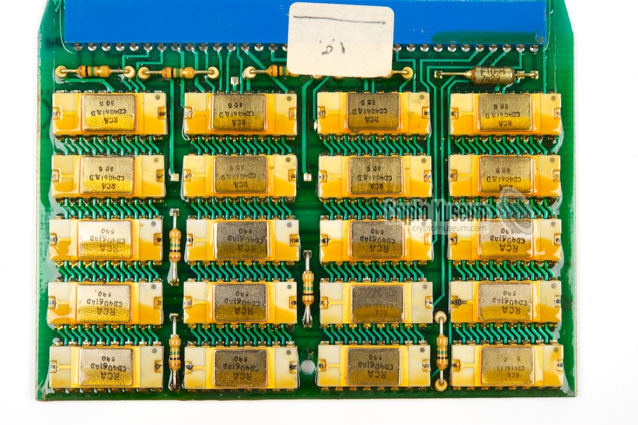
The third board
from the top contains the actual memory, which consists of
20 CD4061AD
chips made by RCA
in the US. Each chip has a capacity of
256 bits (64 bytes) and had a price tag of $200 each in 1974 [3].
This means that the 1280 byte
memory board holds $4000 worth of chips!
The CD4061AD
was introduced in 1974 and was initially only available to
selected customers. The chips shown here were manfactured
in 1975 [2].
The CD4061 is pin compatible with Intel's 1101 RAM, but consumes
much less power, making it ideal for portable battery-powered applications.
|
|
|
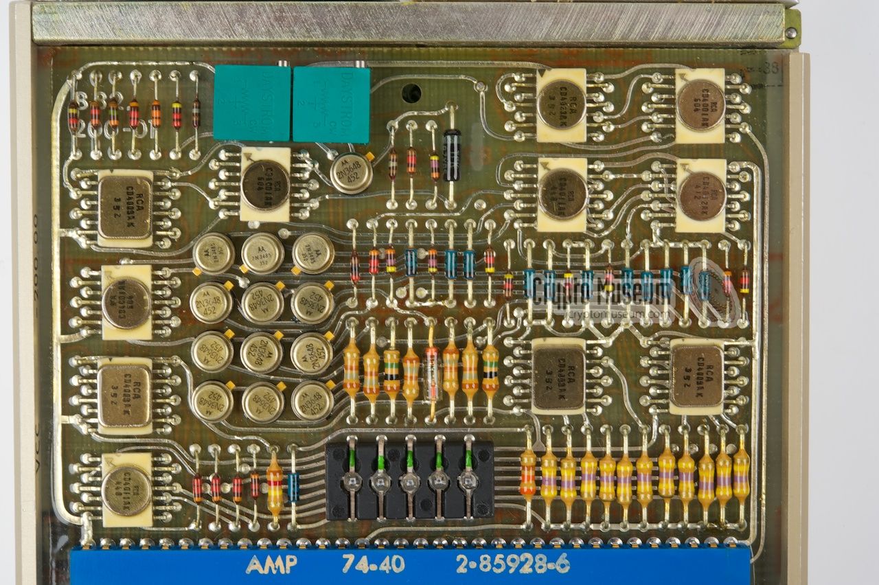
The other boards contain various logic circuits, built around
RCA 's popular
CMOS 4000 series ICs. Note the typical
zig/zag arrangement of the contact pins,
compared to the more common Dual In-Line (DIL)
arrangement. The upper board
contains the actual keyer and the interfaces to the outside world.
The function of each board is printed to the side of the frame (top to bottom):
|
- Ground
- Output (shorted with R)
- Output (shorted with M)
|
|
If you know more about this device, or if you have
documentation about it, please contact us.
|
|
|
|
Any links shown in red are currently unavailable.
If you like the information on this website, why not make a donation?
© Crypto Museum. Created: Thursday 08 October 2009. Last changed: Tuesday, 18 March 2025 - 08:46 CET.
|
 |

|
|
|


