|
|
|
|
|

|
|
USSR
Electronic burst encoder - 1975
R-014D (Russian: Р-014Д), codenamed Datchik (Датчик),
is an electronic high speed information transmitter,
or burst encoder,
developed around 1975 in the former Soviet Union
(USSR). It was used by Soviet Special Forces (SF) during the
Cold War in
conflict areas like Afghanistan. It allows battlefield commands,
in particular coordinates for artillery and air strikes,
to be transmitted digitally at high speed, with low probability of detection (LPD)
through radio direction finding (RDF).
For increased accuracy, the device features advanced error-detection
as well as error-correction.
The R-014D was also a secret element of the
R-142 integrated HF/VHF mobile radio station.
|
The R-014D is a fully self-contained device. It can be powered
by an external 4.8V DC source, such as the TE-20 PSU,
but also from the built-in battery pack. The device is
connected directly to the morse key input 1 of a transmitter,
e.g. the R-130, and transmits data at 75 or 150 bps.
The image on the right shows a typical R-014D. At the front
is the keyboard that consists of 16 rubber keys.
The dark rectangle at the centre is the lamp panel that is
used when entering data.
Behind this panel is the battery compartment.
The input power supply should never exceed 5V.
|
|
|
Like most Russian devices of the era, the front panel of
the D-014D is finished with grey hammer paint. The case however, has
the typical Russian military yellow/green colour, indicating
stand-alone use of the device in the field. It was
used, for example, by the Russian Special Forces (Spetsnaz) [1]
in Afghanistan during the Soviet-Afghan War (1979-1989) [2].
According to Steven Zaloga [7], the R-014D was also installed in
the Russian BRM tank — the reconnaissance version of the
BMP-1 infantry fighting vehicle (IFV) —
where it was used alongside the R-130 radio set.
Each message can be 62 digits long and consists of a 3-digit address,
followed by one or more commands, with a maximum of 59 digits.
Quintuple redundant error detection and correction (EDC) is used,
based on the Bose-Chaudhuri 2 coding scheme, to provide strong noise
immunity [8][9].
The duration of a transmission is 4 to 7 seconds, depending on the selected
speed (150 or 75 baud).
The R-014D is only suitable for the transmission of commands.
At the recipient's end, an R-014P
(Russian: Р-014П) is required
to receive, decode and display the information.
The R-014 was first manufactured in 1975 and was in production until
~ the mid-1980s. It was used by the armed forces of the former
Soviet Union (USSR)
and by the countries of the former Warsaw Pact.
The device shown here was delivered to the Hungarian People's Army
on 31 January 1980, as indicated by the
delivery certificate that was found
inside the device's transit case [E]. 3
|
 |
-
The digital output of the R-014D is connected in parallel with the
morse key input of the transmitter. Depending on the selected transmission
mode, it will generated CW or FSK output. Note that the data sent
by the R-014D is not morse code, but a
proprietary digital format.
-
Bose-Chaudhuri, or Bose-Chaudhuri-Hocquenghem,
commonly known as BCH code,
is a cyclic error-correcting code constructed using finite fields. It was
invented in 1959 by Alexis Hocquenghem in France, and independently in
1960 by Raj Bose and D.K. Ray-Chaudhuri [9].
-
On some Hungarian R-014D units, the instruction plate (on the battery
compartment lid) is in Hungarian, but on the one shown here, it is in Russian.
|
Installing and operating the R-014D is pretty straightforward.
Power source and transmitter are connected to the sockets at
the right. The device is switched on with the black switch at
the bottom right marked ПИТАНИЕ. At the bottom left
is a 4-position rotary switch marked РЕЖИМ which is
used to select the desired mode of operation. The leftmost two
positions are used for selecting 75 baud, whilst the rightmost
two position select a transmission speed of 150 baud.
The settings '1' and '2' are used to select the appropriate
interface for the radio station in use.
Above the MODE selector is another rotary switch,
marked КОНТРОЛЬ (kontrol), that is used
in combination with the meter above for checking the internal
voltages of the device.
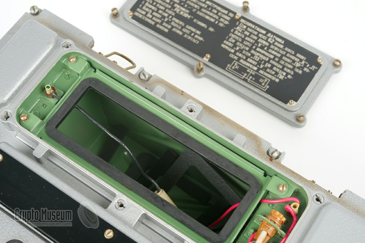
The lamp panel, located at the center of the device, consists
of 12 lamps, marked 0-9, П and K.
When entering a message, the lamps indicate which number
is pressed. Lamp П indicates that the space key is
pressed. When finishing a message (pressing the КЦ
key) lamp K should light up.
|
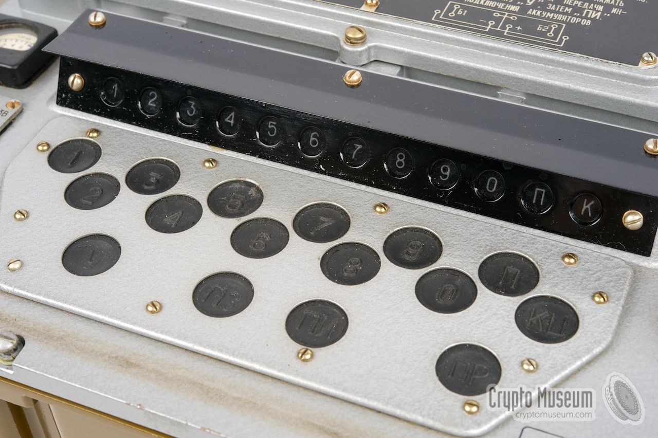
The keyboard is fully waterproof and consists of 16 keys
with rubber key tops. On each key top the corresponding
number or letter is embossed. In the dark however, it might be
difficult to read the embossed characters, which is why
it is shown with white lettering in the drawing below.
|
|
Before a (short) message can be stored in the Datchik, it first has
to be converted from letters to numbers, as the device is only
capable of storing digits. This was usually done by means of a
message substitution table or
letter matrix.
It is currently unknown which substitution scheme was used for this.
If you have any information about this, please contact us.
|
- Set the mode switch РЕЖИМ to the correct position
- Press У followed by the data (numbers 0-9), 62 characters max.
- Use П to insert spaces wherever necessary (e.g. after each group)
- Press КЦ to terminate the message (if less than 62 characters are used)
- Press У followed by ПР to check the input (optional)
- Press У followed by ПЗ to send a synchronize command
- Press У followed ПИ to send the message
|
By default, the R-014D is used for unidirectional (one-way) transmission
of numeric data, such as artillary coordinates for which error-free
reception is paramount. In that case, the R-014D is connected directly
connected to a transmitter, and no confirmation of reception is expected.
This unidirectional setup was used in all countries of the former Warsaw Pact.
At the remote end, the R-014P burst receiver is used for decoding and
displaying the data.
In combination with radio stations R-135, R-137 and R-140, it is possible
to create a bidirectional (two-way) setup by adding the R-014P to
the setup. In this situation, the R-014D is slaved to the R-014P as shown in
the diagram below. The 4.8V power supply is also provided by the R-014P.
As far as we know, the burst receiver — R-014P — was a Russia-only device
that was not supplied to other Warsaw Pact countries. Photographs of an
R-014P would be much appreciated.
|
|
German radio amateur Karsten Hansky, was so kind to send us an R-014D
sound sample, that he recorded in May 2016 when sending data with his
R-014D via an R-143 (Bagulnik) radio set, on 3573 kHz at 75 baud [5].
The sound sample can be played below and can also be downloaded.
|
|
The R-014D is suitable for sending burst messages at 75 or 150 baud,
via a variety of radio sets. The desired speed and radio set should
be selected with the MODE selector (РЕЖИМ) before starting a
transmission. The following radio sets are known to be supported [6]:
|
- R-137, R-140
- R-129, R-130, R-130-03, R-131, R-135, R-143 (Bagulnik)
|
|
During the Cold War,
most countries of the Warsaw Pact used a
variety of Russian communication vehicles and radio stations.
To allow communication in the vicinity of the vehicle (short
range) as well as over greater distances (long range), such
radio stations were often equiped with HF, VHF and sometimes
even UHF transceivers. They were usually placed inside trucks
like the GAZ-66.
|
A good example of a complete radio station is
R-142.
It consists of a large metal frame with a variety of transceivers,
control panels, intercom systems, amplifiers and switch boxes. It
could be used stand-alone as a base station, but was often
built inside a shelter mounted on a GAZ-66.
The image on the right shows the interior of the communications
shelter. Apart from a collection of HF/VHF radios and
audio switch panels, there is room for three secret devices.
The first one is the
M-125 (Fialka) cipher machine,
that is placed in the empty spot right in front of the operator.
|
|
|
A complete R-014D kit was supplied in a grey wooden transit case,
such as the one shown in the image on the right. It measures 550 ×
340 × 320 mm and weighs 24 kg including all parts.
The lid is held in place by four spring-loaded clamps; two at the front
and two at the rear. Inside the case are
two compartments:
one for the radio and the documentation, and one for the cables.
|
|
|
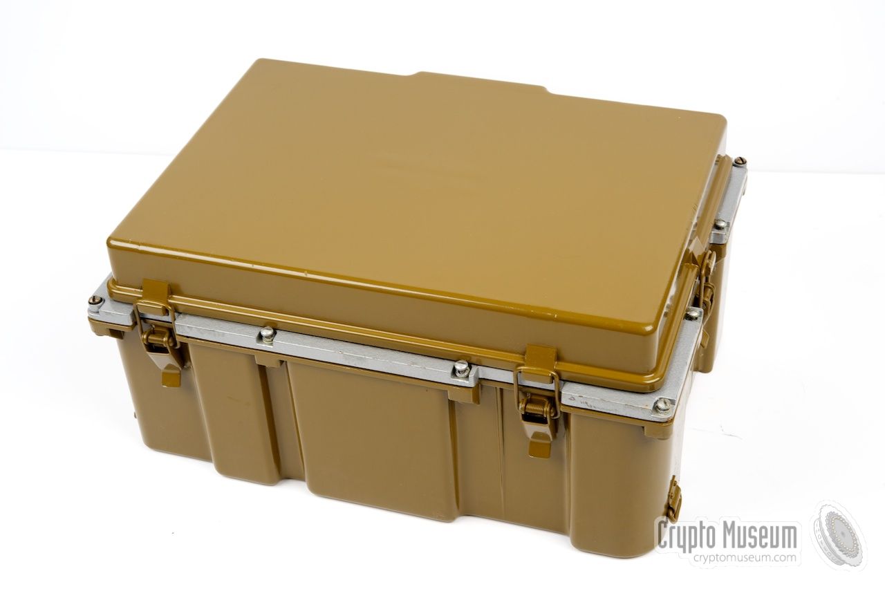
The actual R-014D burst encoder is housed in a watertight enclosure,
with a rubber-sealed lid to protect the controls agains water.
The lid is held in place with 6 spring-loaded locks: two at the front,
two at the rear and one at either side.
The image on the right shows the bare unit, without its protective
lid. It is powered by two internal batteries, or by an
external 4.8V DC source.
|
|
|
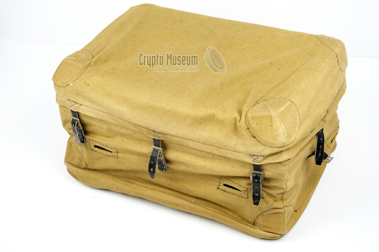
When the device was used by Special Forces (SF), for example in
conflict areas like Afganistan, it was usually carried inside the
canvas 'raincoat' shown in the image on the right.
The canvas coat can be attached to the webbing and has a
compartment for stowing the cables.
A separate canvas strap was supplied, to allow the device to be carried
from the shoulder.
|
|
|
A short 1.5 metre power cable was supplied with the R-014D.
It was used when the device had to be powered externally.
It has a 2-pin plug at the device end, and a 5-pin military
plug at the other end.
➤ Wiring of the power socket
|
|
|
The R-014D could be connected to most regular transmitters (radio sets)
by means of the interconnection cable shown in the image on the right.
Both ends of the cable are fitted with an identical 5-pin plug.
The cable is wired 1:1.
Although the cable shown here is marked for use with the R-130M radio,
it can be used with most other radios that accept the same connector.
➤ Wiring of the radio socket
|
|
|
Each R-014D came with a full set of documentation, consisting
of a passport, operating instructions, a technical description
and a full set of circuit diagrams, each bound in a red cover.
Unfortunately, most of the surviving manuals
have faded considerably over time, to the point where they are
no longer readable. 1 The set
shown here is in good condition and is available for download below.
➤ Download documentation
|
|
|
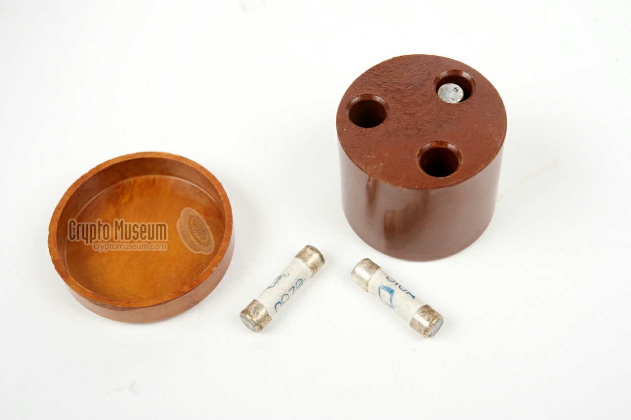
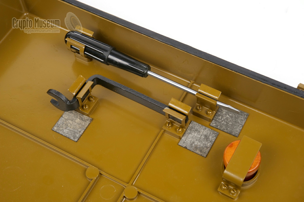
Inside the top lid are two tools — a screwdriver and a wrench —
plus a small bakelite can with three spare fuses.
The screwdriver can be used to open the battery compartment.
The fuse is also located there.
The wrench can be used to mount the battery terminals.
It is advised not to use the screwdriver, as its grip is made of the first
generation of plastics that were available in the Soviet Union.
These plastics are known to be unstable and may become brittle over time.
|
|
|
|
The diagram below shows a greatly simplfied block diagram of the structure
of the R-014D. At the left is the keyboard (yellow) that has 16 push-buttons,
10 of which are used for the digits 0-9. The output of the keyboard is
converted into a 5-bit digital code by the Encoder. To allow
error checking, each digit consists of exactly three '1' bits and two '0' bits.
The output of the encoder is stored in a memory unit with 63 positions
(7 x 9). When transmitting, the data is read from the memory unit and
converted into a serial data stream by the serialiser (red) and then
filtered.
|
Each of the 12 buttons on the keyboard, generates a 5-bit digital code
of which 4 bits are used for the character (i.e. the pressed button) and
one bit for (odd) parity. The latter allows for error checking in later
stages, such as the memory and the serialiser.
The 5-bit codes for the digits 0-9 all have exactly three '1' bits and two
'0' bits. The codes for the space and the end of message characters,
each have exactly one '1' bit and four '0' bits. The table below shows the
encoding for each character (note that the device uses negative logic).
|
| Character | bit 1 | bit 2 | bit 3 | bit 4 | bit 5 | Remark | '1' bits |
|
|
| 0 | 0 | 1 | 1 | 1 | 0 | | 3 |
| 1 | 1 | 0 | 1 | 1 | 0 | | 3 |
| 2 | 0 | 0 | 1 | 1 | 1 | | 3 |
| 3 | 0 | 1 | 0 | 1 | 1 | | 3 |
| 4 | 1 | 0 | 0 | 1 | 1 | | 3 |
| 5 | 1 | 0 | 1 | 0 | 1 | | 3 |
| 6 | 1 | 1 | 0 | 0 | 1 | | 3 |
| 7 | 1 | 1 | 0 | 1 | 0 | | 3 |
| 8 | 1 | 1 | 1 | 0 | 0 | | 3 |
| 9 | 0 | 1 | 1 | 0 | 1 | | 3 |
| Space | 0 | 0 | 1 | 0 | 0 | Пробел (ПР) | 1 |
| End | 0 | 0 | 0 | 1 | 0 | Конец (КЦ) | 1 |
| | parity | |
|
Messages are stored in a set of three non-volatile core memory devices.
Reading a bit is destructive, which is why a refresh circuit
is present. It ensures that each time a data word is read, it is written back.
When the device is switched off, the message is held in
memory for a long time, even if no power is present.
This is not a desired feature but rather a propertly of core memory.
Each of the three memory blocks contains three core memory banks,
each of which is organised as a 8 × 6 matrix. In the R-014D it is
used however as a 7 × 5 matrix (one row and one column are unused).
This is done as the data is stored in 5-bit format. The fifth bit is
the (odd) parity bit.
The diagram above shows how the memory is addressed.
At the top is the bank selector, which allows one of the 9 available
banks to be selected. At the bottom is the address selector, which consists
of 7 lines. This means that a total of 9 × 7 = 63 words is available,
which is suitable for 3 address words, 59 data words and one terminator (End).
At the left is the input data word, of which all 5 bytes are written
simultaneously during a write cycle. The output is at the right.
In the circuit diagrams, the bank (column) selector and the address (row)
selector are designated коммутатор (commutator). They contain a series of pulse
transformers that allow a pulse to be passed through the cores in
forward or reverse direction. This is necessary, as the polarity of the magnetic
field – held by the hysteresis loop property – represents the logic '0' or '1'
state [12].
Reading is done by forcing all bits of a word to '0', whilst observing the
state of separate sense wires that are also woven through the cores.
Only when the state changes from '1' to '0', a pulse will be induced on the
corresponding sense line. After reading, the contents of the addressed word
will be '00000', which is why additional circuitry is present to rewrite
the word (refresh).
|
The serialiser (i.e. the red block in the block diagram) converts
the 5-bit data words from the memory into a serial data stream,
whilst adding some level of redundancy to it. This is done to enable
error-checking and error-correction. The diagram below shows the construction
of the serialiser, which uses the Bose-Chaudhuri 2 coding scheme to provide
strong noise immunity [8][9].
The memory, which delivers the 5-bit data words to the serialiser, is
shown at the top left.
The 5 data bits are loaded into the first positions of a 14-stage linear
feedback shift register (LFSR 1) and will eventually appear unaltered
at the output of that shift register, with new bits (derived from the current
data) being fed in from the left. The output of LFSR 1 is added (XOR) with
the output from LFSR 2, with has 7 stages (i.e. half te size of LFSR 1).
The diagram also shows the initial state of the LFSR2 register on startup:
1010110.
|
|
Compared to other burst encoders of the same era, the
R-014D is rather large and heavy. It was the first fully
electronic burst encoder developed by the former USSR
and it shows the state-of-technology in Russia in 1975.
In this respect, one should bare in mind that western
technology wasn't available to the Russians at the time.
Heavy use is made of first generation of Russian ICs.
|
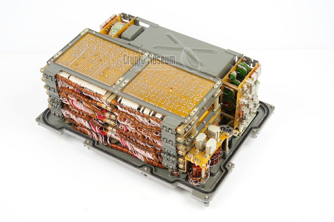
The unit can be opened by loosening the 12 bolts at the edges
of the front panel. Note that two of these bolts might be
sealed with black or red wax. If the wax is still present,
the case has not been opened after the device was released.
Once the bolts have been loosened, the entire interior can
be extracted from the case by lifting the front panel.
Despite the fact that the R-014D can hold only 62 characters
in its memory, it contains a surprisingly large number of parts.
About one-third of the volume is taken by the
battery compartment.
The rest is for the PCBs.
|
|
|
|
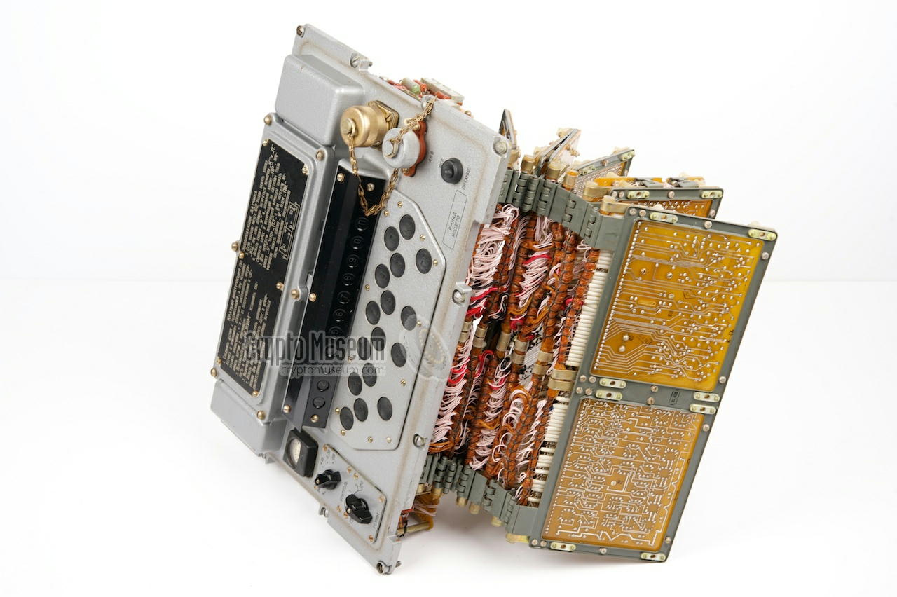
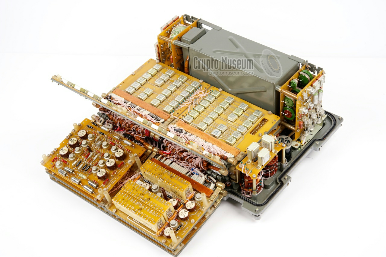
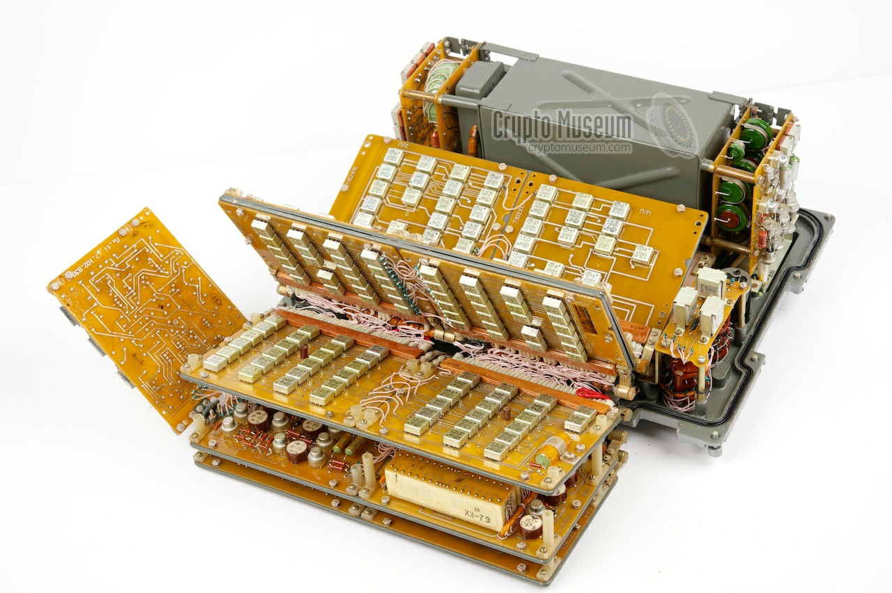
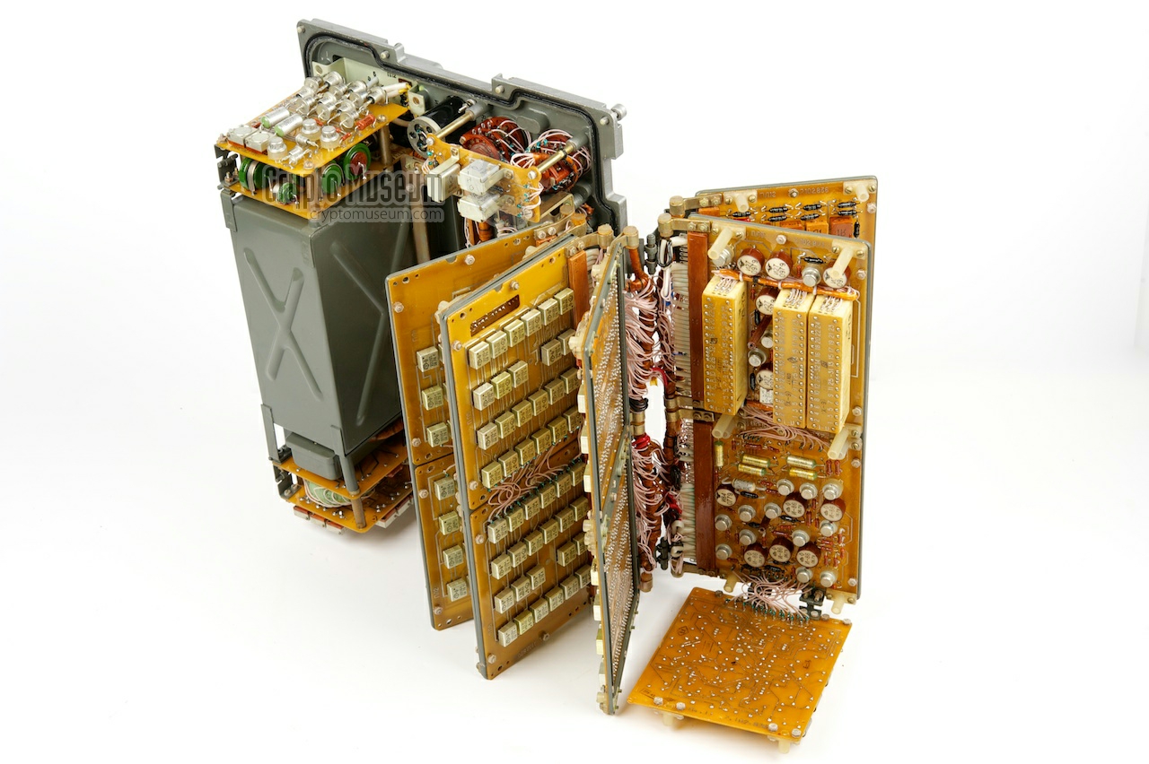
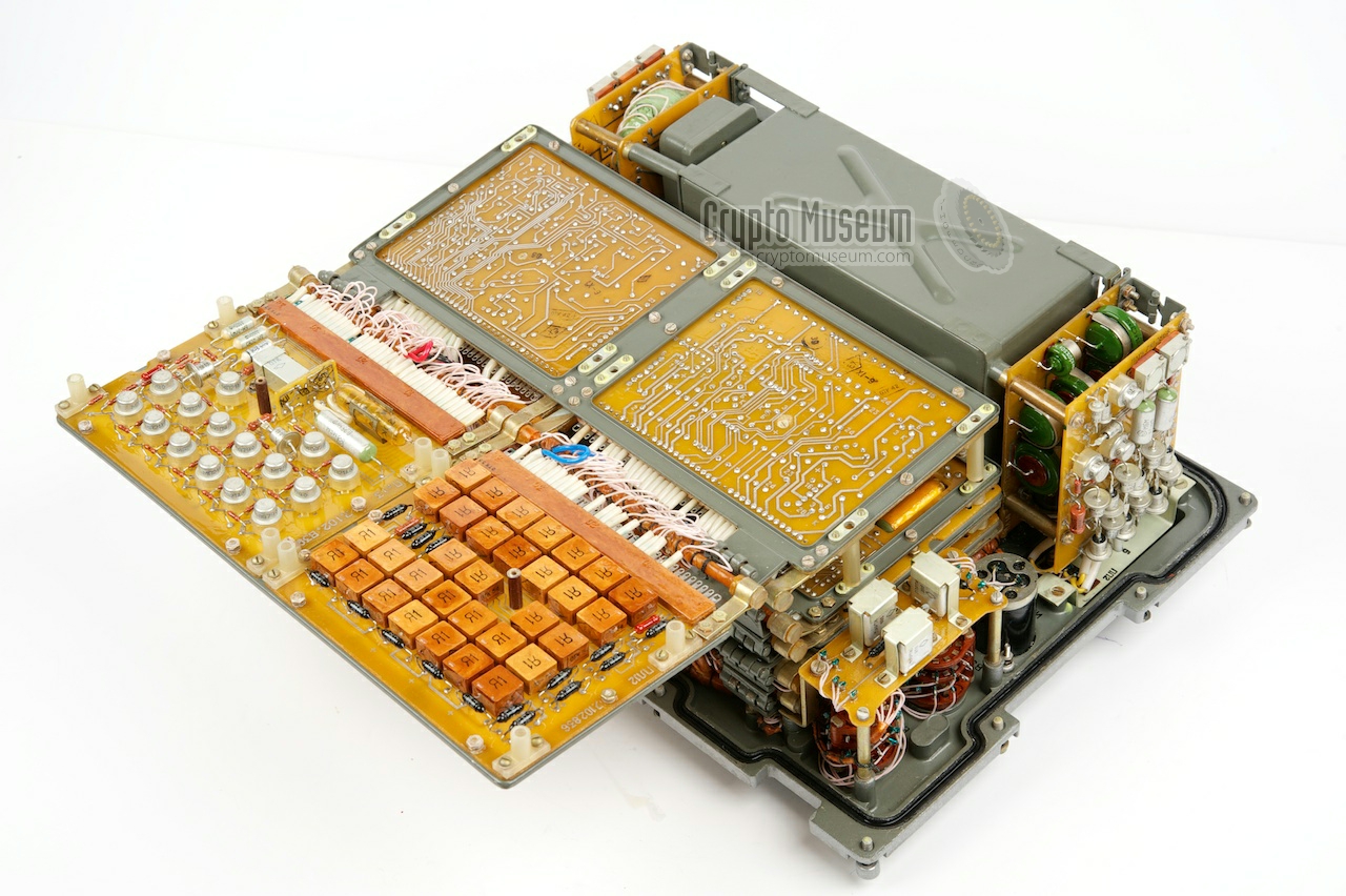
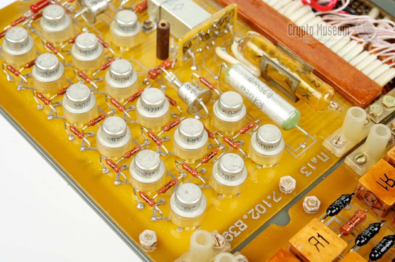
The circuitry is built around a large number of first-generation
Russian Integrated Circuits (ICs) that are spread over 12
small PCBs. The PCBs are all mounted in a six-layer hinged
assembly. Despite its complexity, the R-014D is very service-friendly.
After removing the 8 long bolts that hold the PCBs together,
the stack of boards can be
'browsed' like the pages of a book.
|
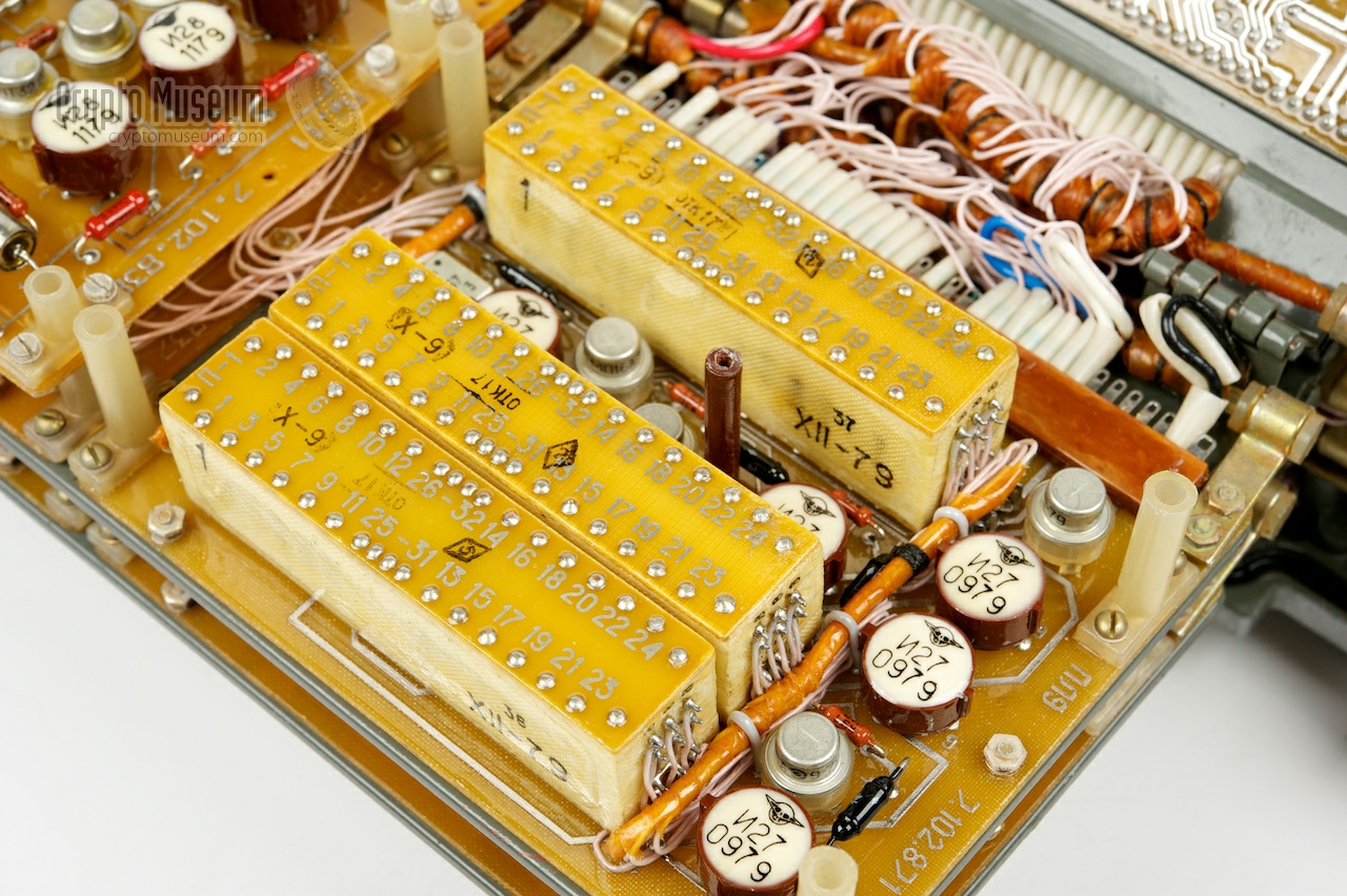
The square metal hybrids that are visible in the image above,
are general-purpose logic devices of the 201-series, based on RTL
technology [10] and made by the Exiton factory (Экситон) in
Pavlovski Posad (Moscow District, Russia) [11].
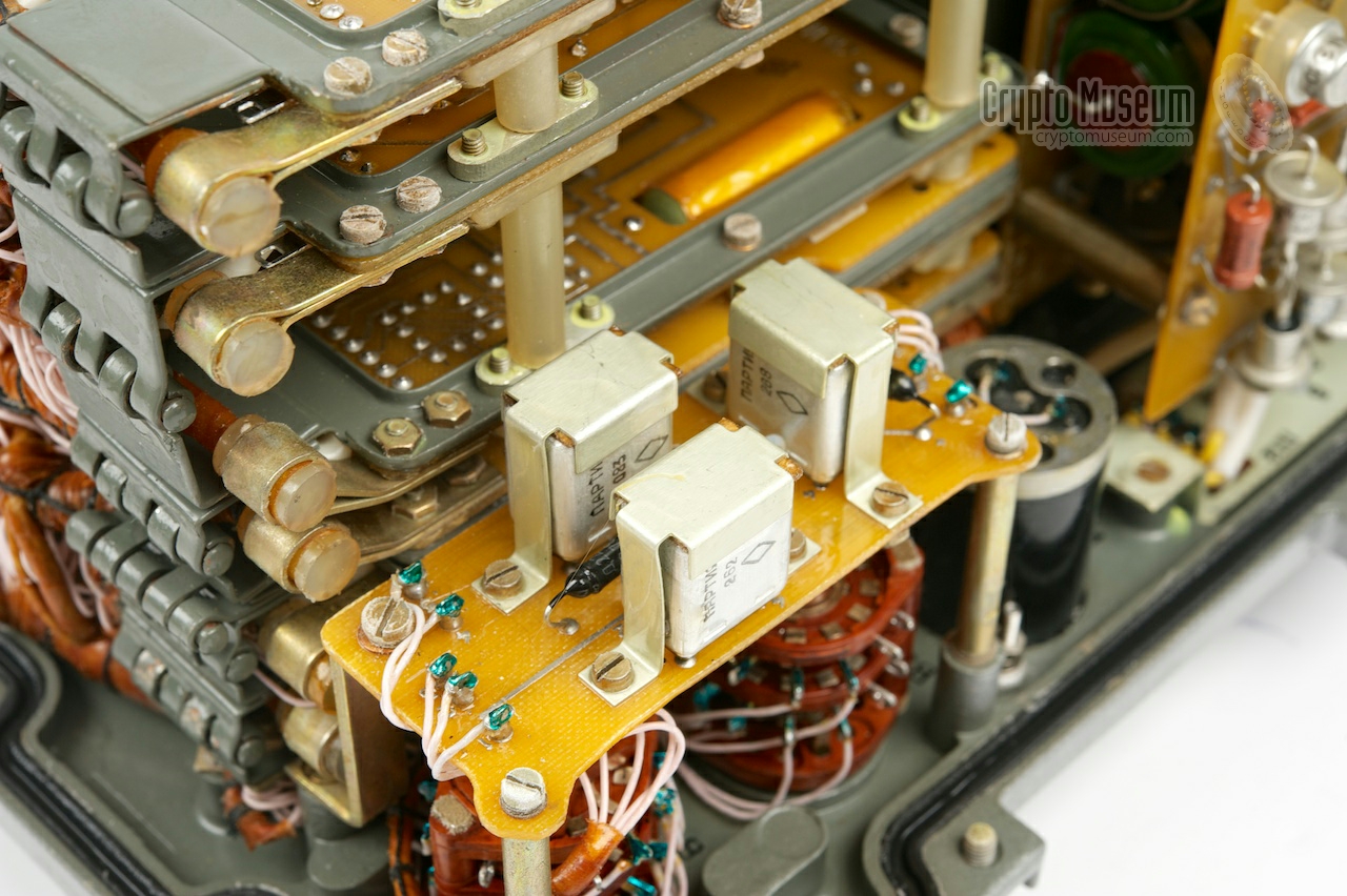
The messages are stored in a set of
non-volatile memory devices that are
located on the second PCB,
complete with write, read and refresh circuits.
Such memory devices consist of a series of miniature circular
ferro-magnetic cores, each of which can hold 1 bit of information
by using the hysteresis loop properties of the ferrite material.
|
|
|
|
Reading a bit is destructive, which is why a refresh circuit
is present. It ensures that each time a data word is read, it is written back.
When the device is switched off, the message is held in
memory for a very long time, even if no power is present.
|
|
Below is a translation of the original checklist
that was supplied with each R-014D. It shows which items were suplied,
how many of each, and in which compartment of the
wooden transit case they were stowed.
Thanks to Jerry McCarthy for the translation [13].
|
|
The diagram below shows the pinout of the output connector on the front
panel of the R-014D, when looking into the socket from the front of the
device. The diameter of the connector is approx. 25 mm.
In most cases, a 1:1 cable was used for connection to the transmitter.
|
- Relay contact (1)
- Signal out
- -
- Relay contact (2)
- Ground (and shield)
|
|
|
Power for the R-014D is usually derived from the power supply unit that
comes with the radio, and is typically 4.8V. Alternatively, the unit can
be powered by internal batteries that should be fitted below the large
lid on the control panel. In any case the source should not exceed 5V.
Below is the pinout of the power connector when looking into the socket.
It has a thick and a thin pin. The thin one is connected to ground.
The thick one goes to the + terminal of the battery.
|
Device Burst encoder Purpose Error-free transmission of artillery coordinates Model R-014D (Р-014Д) Codename Datchik (Датчик) Country Soviet Union (USSR) Year 1975 Users USSR, WP, Spetsnaz Memory 62 characters 1 Speed 75, 150 baud Burst 4 (150 baud) or 7 (150 baud) seconds Accuracy ±1% Clock 120 kHz Stability 5 × 10⁻¹ Output 5V (into 1KOhm), 10V (into 5 KOhm) Warmup 2 minutes Power 4.8V DC +10/-15% - 2 × 2NKP-20U2 (2НКП-20У2) @ 2.5V
Internal +4V, -6.3V, -20V Consumption 1.5A (standby), 2.1A (transmit) at 4.8V DC Temperature -50°C to +50°C Dimensions 351 × 251 × 168 mm Weight 14.5 kg
|
-
3 address characters and 59 message characters.
|
low: 0-0.15V high: ≥ 5V into 1kΩ low: 0-0.5V high: 10V ±2.5V into 5kΩ
|
7326 1977 Crypto Museum 8120 1979 ~ Private collector Germany 8140 1979 ~ Crypto Museum 8423 1979 ~ Privte collector Austria 8776 1980 Crypto Museum
|
-
Kindly dontated by anonymous contributor (2008) [4] and scanned by Crypto Museum (January 2024).
|
- Wikipedia, Spetsnaz
Russian Special Forces. Retrieved October 2013.
- Wikipedia, Soviet-Afghan War
Retrieved October 2013.
- Helmut 'Jim' Meyer (HS0ZHK), My way to Ham - Radio and beyond
Website QRZ.COM. Personal correspondence.
Retrieved June 2008.
- Anonymous contributor, Original R-014D documentation, 1975
Received June 2008.
- Karsten Hansky, R-014D sound sample
Recorded with R-143 (Bagulnik). Received May 2016.
- Jörg Drobick, Datschik Funk Schnelltelegraphie mit Verschleierung
Website Der SAS- und Chiffrierdienst (SCD). Retrieved May 2016.
- Steven J. Zaloga, BMP Infantry Fighting Vehicle 1967-94
June 2013. ISBN 9781472804556. p. 74.
- Russianarms.SU, Technical literature
Website. Retrieved May 2016.
- Wikipedia, BCH code
Retrieved May 2016.
- Wikipedia, Resistor-transistor logic
Visited 4 January 2024.
- Wikipedia, Soviet integrated circuit designation
Visited 4 January 2024.
- Wikipedia, Magnetic-core memory
Visited 4 January 2024.
- Jerry McCarthy, Checklist translation
25 January 2024.
|
|
|
|
Any links shown in red are currently unavailable.
If you like the information on this website, why not make a donation?
© Crypto Museum. Created: Monday 22 February 2010. Last changed: Wednesday, 11 February 2026 - 14:41 CET.
|
|

|
|
|
| |


