|
|
|
|
|

|
|
USSR Cold War PR-56 → P-57 →
USSR spy radio set
P-57, codenamed RION, was an
agent communication device, or
spy radio set,
developed in 1957 in the former Soviet Union (USSR).
The device was intended for clandestine operations in foreign countries
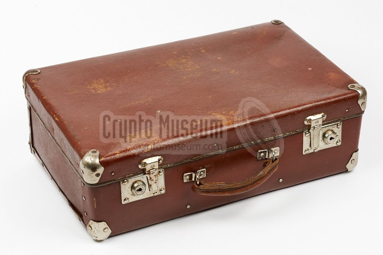
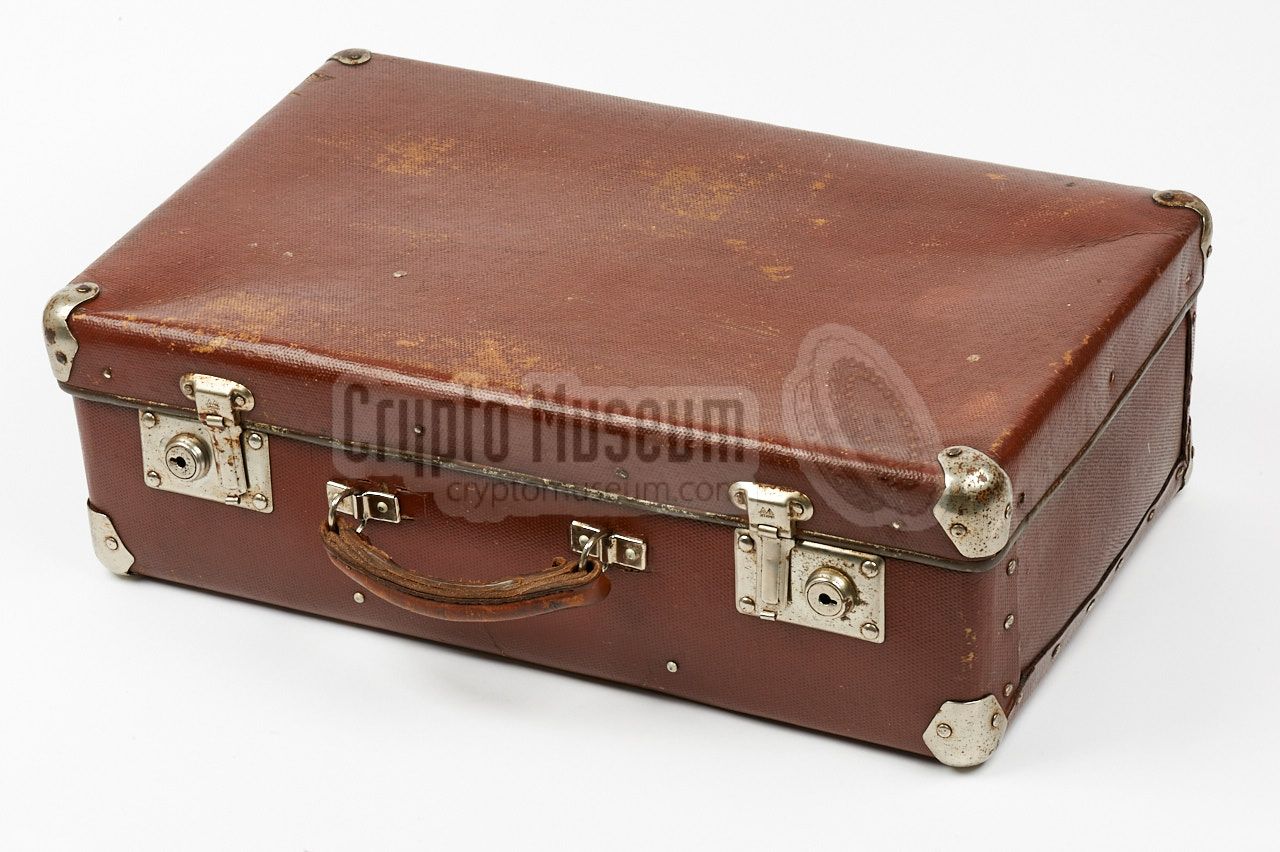
and was generally operated from within its unobtrusive brown
fibreboard suitcase.
|
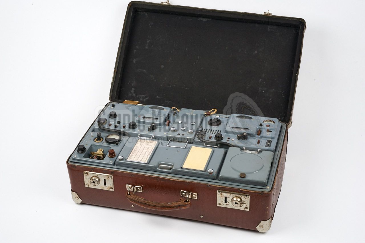
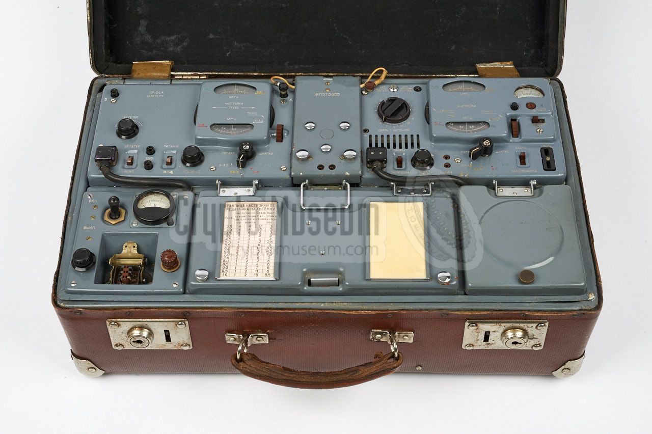
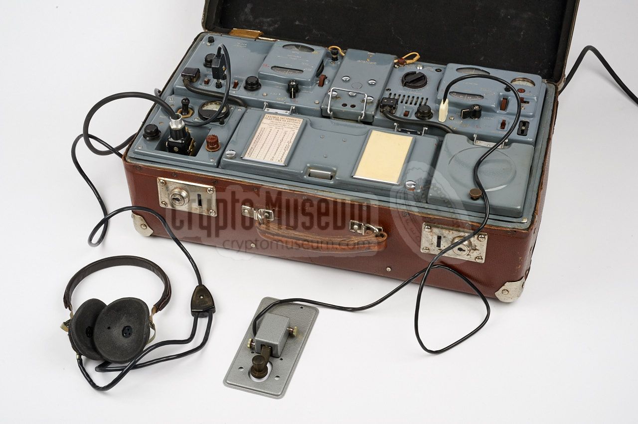
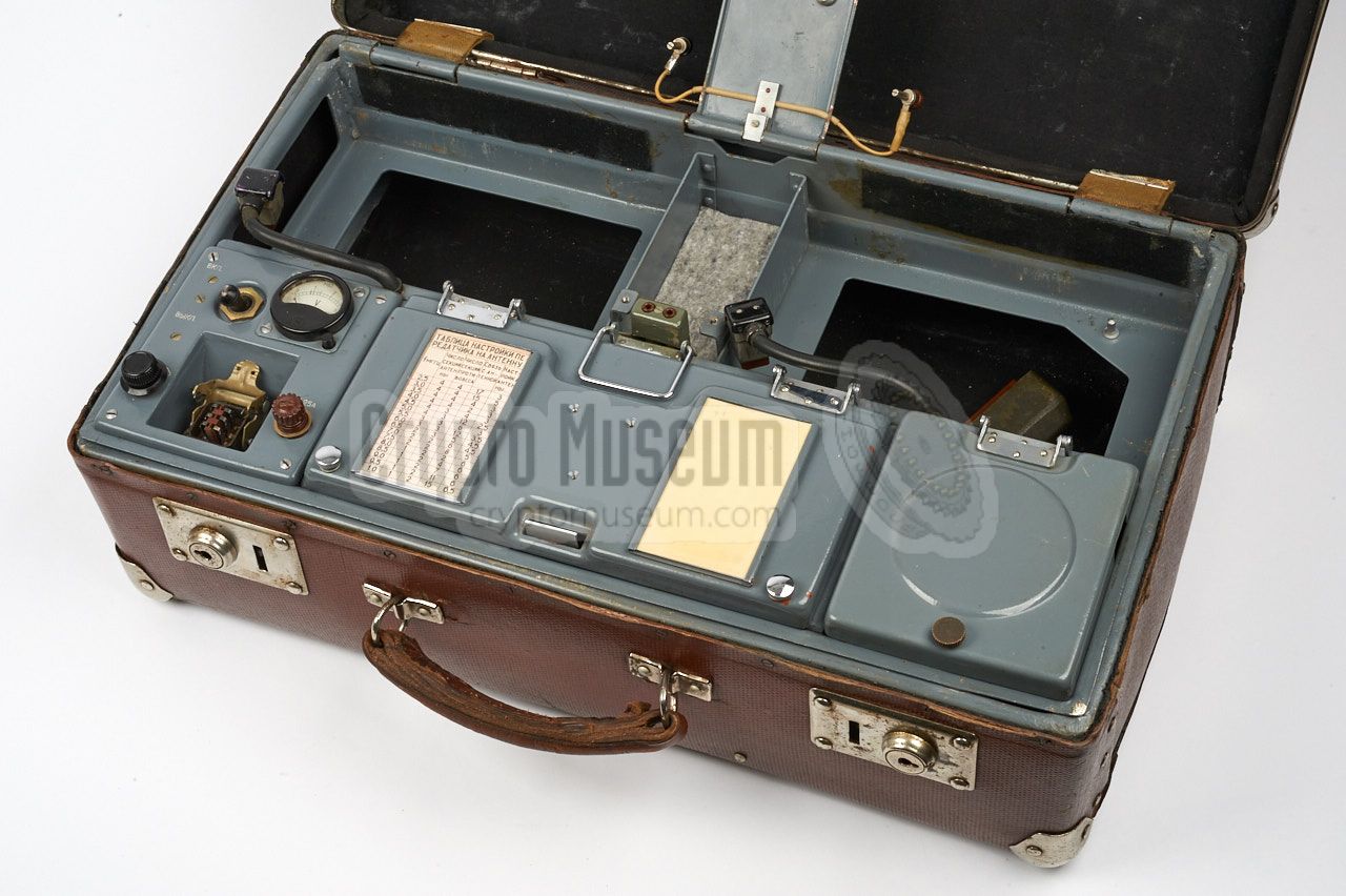
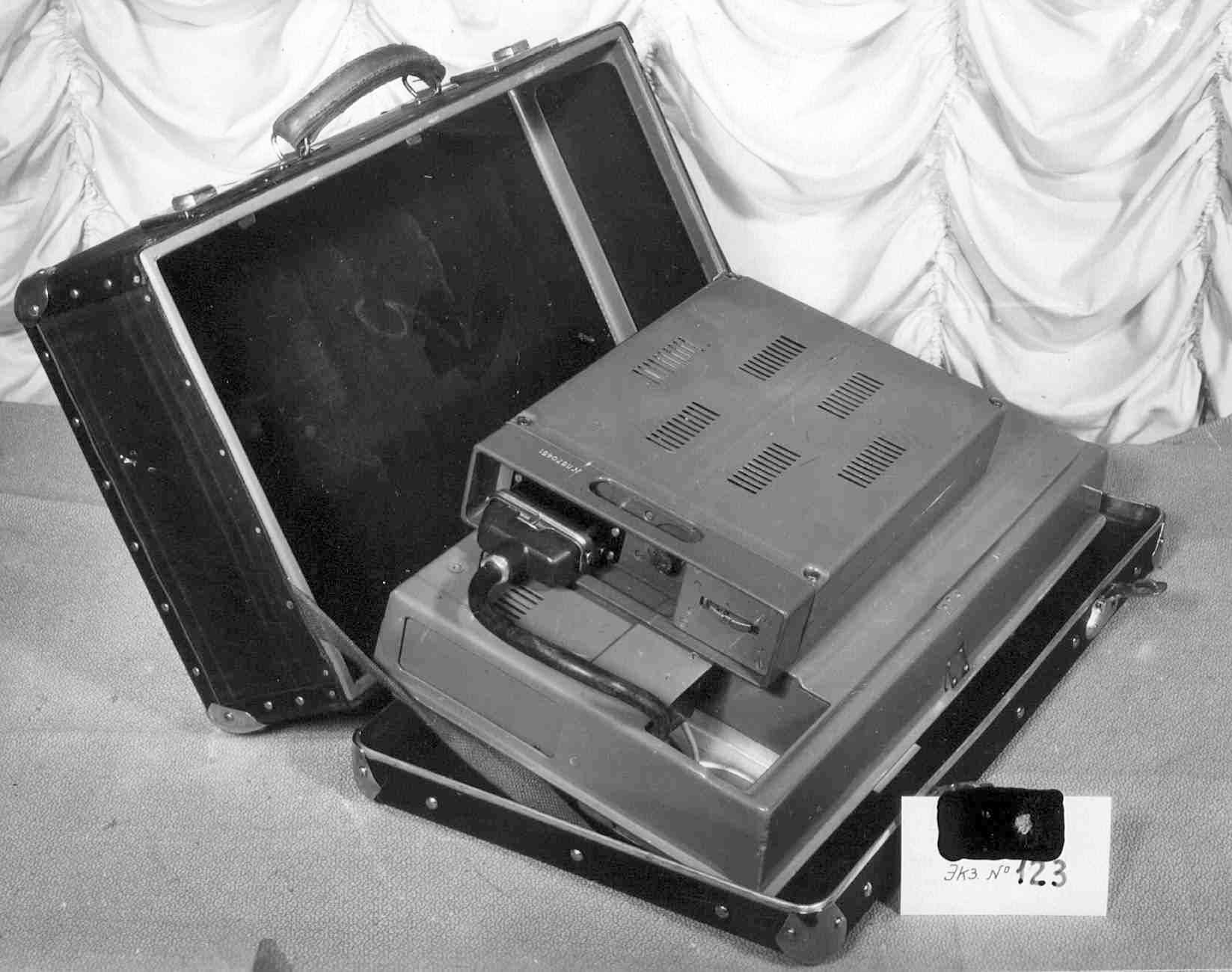
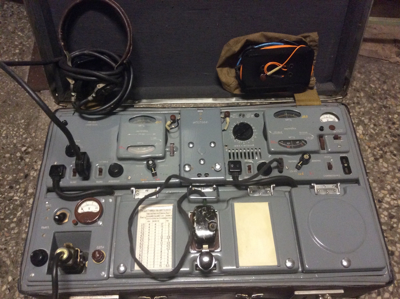
The image on the right shows the complete radio set
mounted inside a standard fibreboard travel suitcase of the era,
similar to the British B2 spy set of WWII [3].
An additional suitcase contained a power supply unit (PSU) and a power inverter.
The device consists of a PR-56A receiver at the top left,
a RION transmitter at the top right, and a mains power supply unit (PSU)
at the bottom left. The rest of the space is filled with a spares box and
a cable storage box. In the image on the right, a small morse key, connected
to the RION transmitter, is fitted on top of the spares box.
|
|
|
The transmitter is suitable for the 2.5 to 10 MHz frequency range and delivers
an output power of approx. 10 Watts in CW (morse).
It can be crystal operated, but is also freely adjustable by means of a
built-in VFO. The receiver is suitable for the reception of CW signals between
2 and 12 MHz. The set can be used in simplex or in half-duplex mode.
In the latter case, separate RX and TX antennas have to be used, with
sufficient distance between them.
In the former case, a single wire antenna is connected to the transmitter,
which is then shared with the receiver via a loop wire.
|
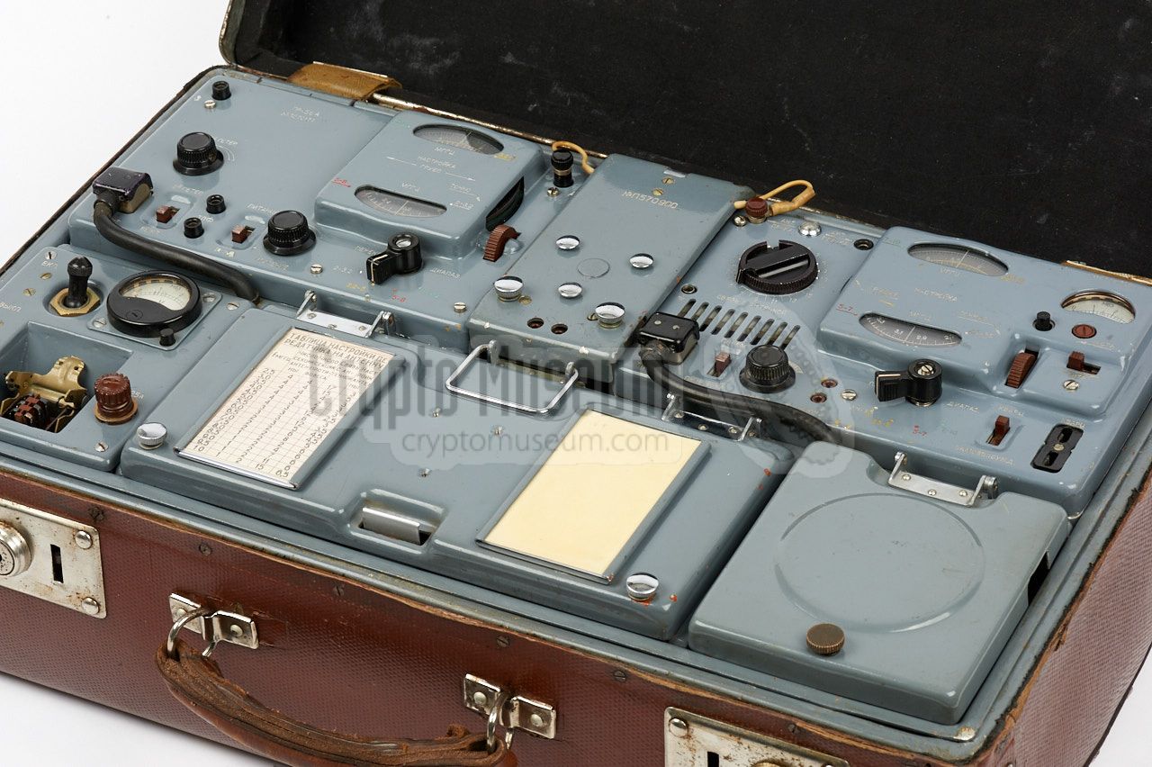
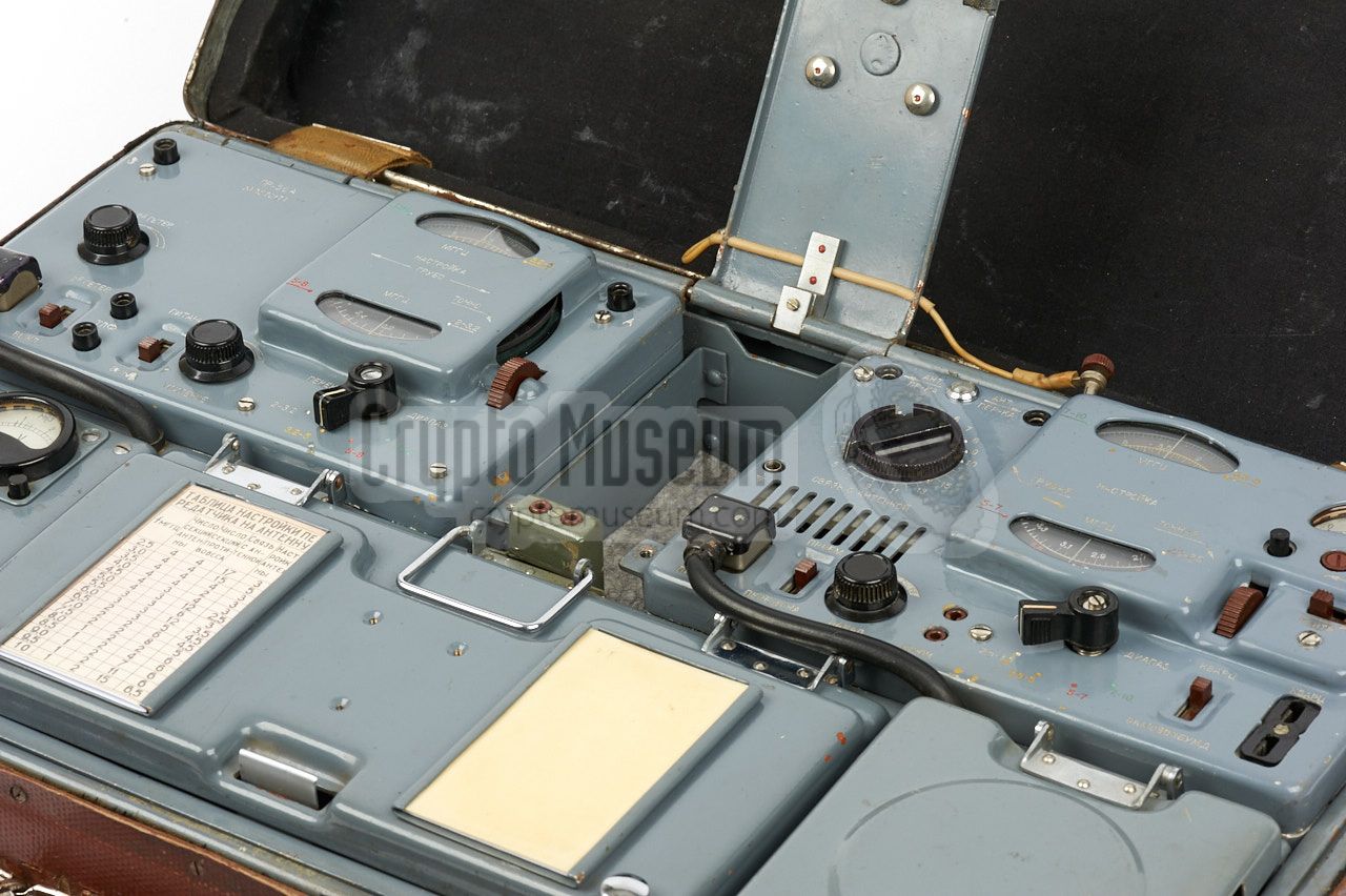
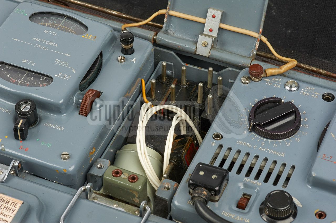
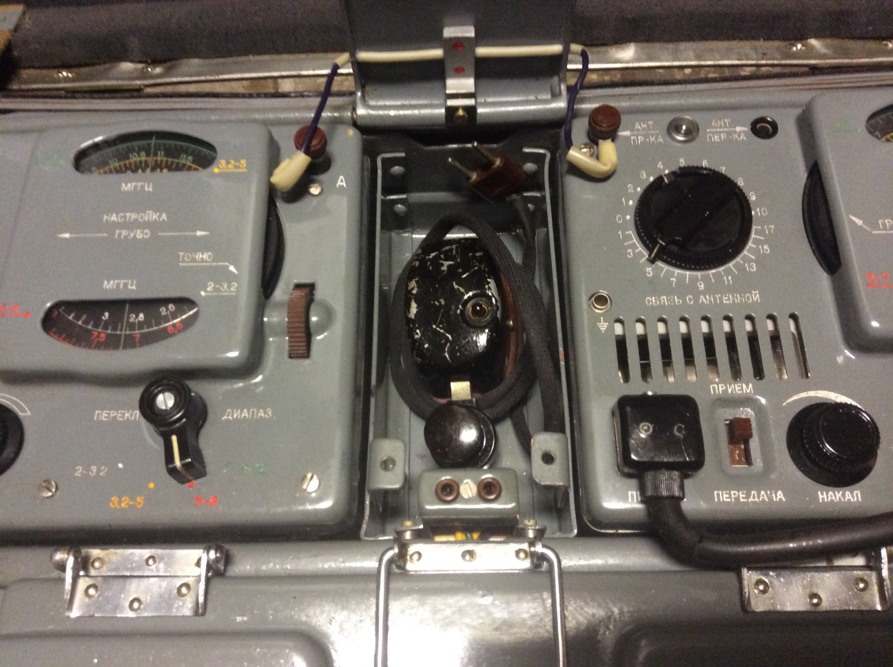
The diagram below gives an overview of the many controls and connections
of the radio set. At the bottom left is the power unit to which the mains
power cord (or an alternative power source) should be connected. It has a
meter for checking the internal 1.5V LT and 240V HT power rails.
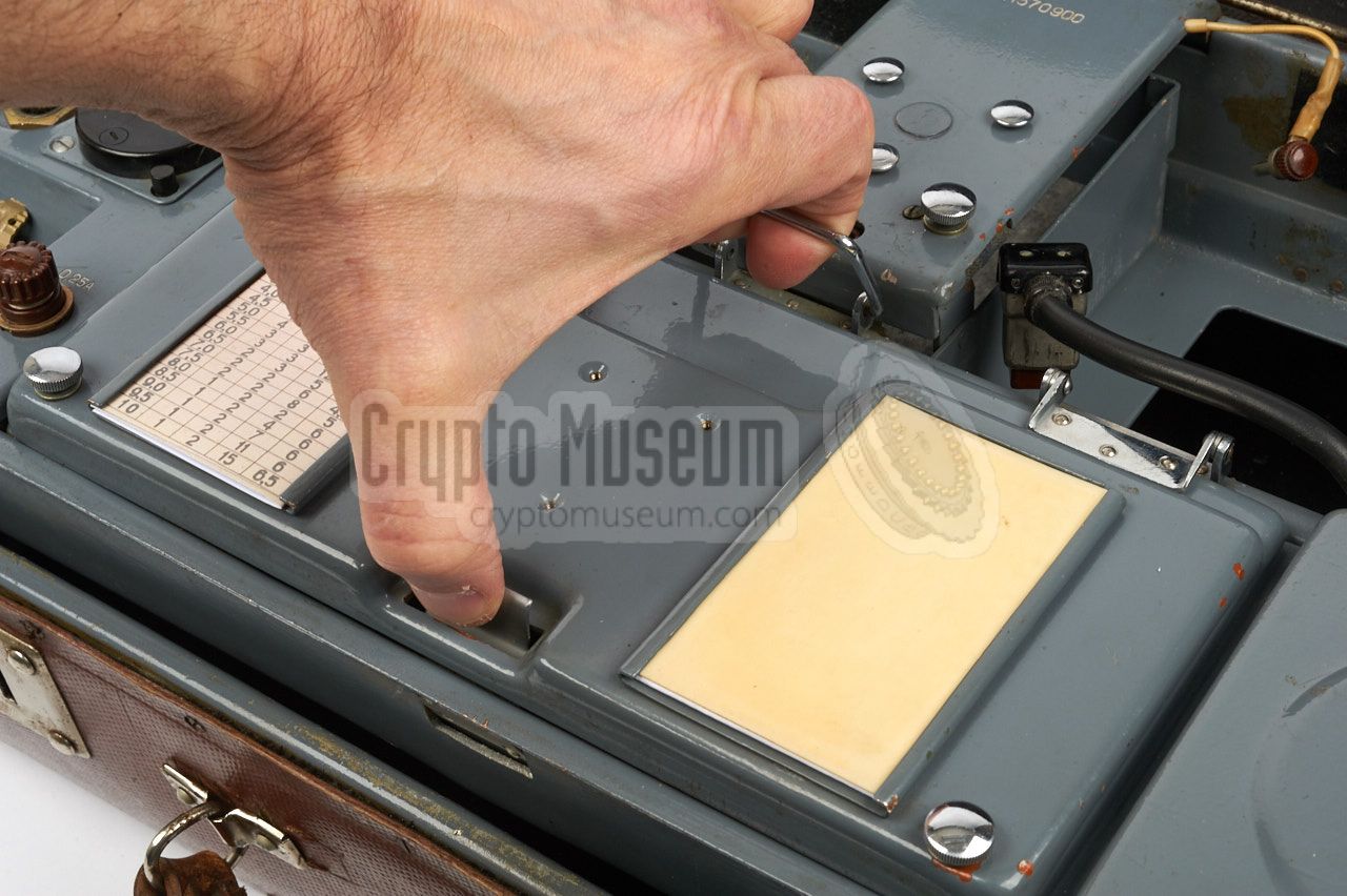
The receiver and transmitter are two separate units that are installed
in two dedicated bays of a hinged frame. They are held in place by the
lid of the narrow storage compartment at the top centre, and are each
powered by a small rectangular plug at the bottom left. Note that the
pin-out of these plugs are not identical and that the voltages are
different as well. For this reason the transmitter bay has a coding pin
that mates with a hole in the bottom of the transmitter. For a
detailed description of the control, refer to the separate pages
about receiver
and transmitter.
|
A complete RION spy radio station consisted of two leather suitcases.
One with the radio station as shown above, and a smaller one with a
power supply unit and a power inverter (vibrator). The extra suitcase
was intended for use in urban areas where access to a mains AC network
was available.
It will be obvious from the picture below that RION was not a lightweight
radio station.
The weight of the two cases together was approx. 40 kg,
which must have required a quite strong operative.
The set was built to sustain extreme conditions, such as an operational
temperature range from -40°C to +50°C and a relative humidity of 85%.
|
|
RION can be powerd in quite a few different ways, but you should note that
only one of these methods can be used. No matter which option is chosen, it
should always be installed in the empty space at the bottom of the suitcase,
and must be connected to the 14-pin power plug that is available
in the small compartment at the front right of the control panel.
|
- Internal batteries
A large unit with dry battery cells can be mounted to the bottom of the
radio's frame, in the empty space at the bottom of the suitcase. When present,
the batteries directly provide the necessary LT and HT voltages to the
transmitter and to the receiver.
- AC Mains
The radio can also be powered directly from the AC mains, when the optional
Power Supply Unit (PSU) is installed. The PSU can be fitted in the bottom
section of the suitcase, instead of the batteries. Alternatively, the PSU
can be placed aside the radio. In that case, the 14-pin plug
should be disconnected from the batteries and connected to the PSU.
- External battery
RION can also be powered by a 12V DC source, such as the battery of a car.
In that case, the optional vibrator-based power inverter should be used.
It can be installed in the bottom compartment of the suitcase, or placed
aside the radio, connected to the 14-pin power plug.
The 12V DC source should be connected to the radio's
6-pin power socket.
|
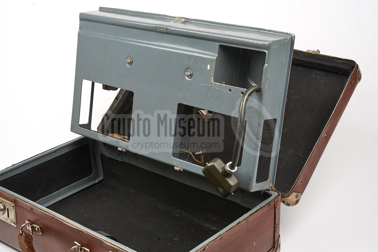
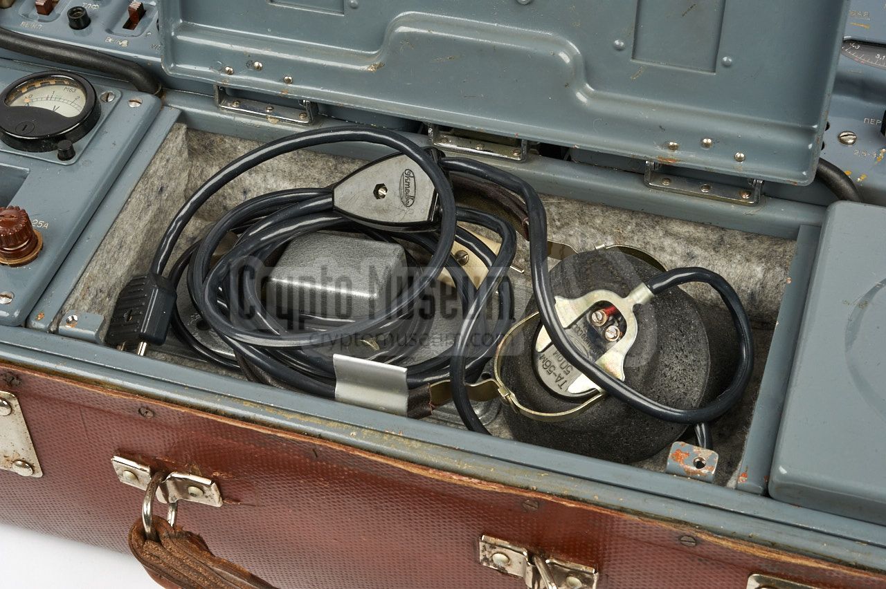
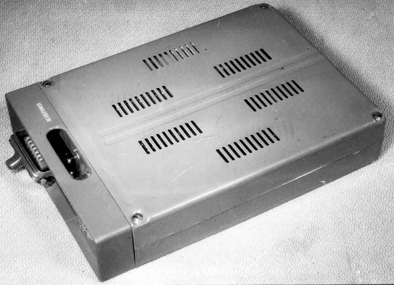
The RION set was supplied in an unobtrusive brown fibreboard (cardboard)
suitcase.
Inside the case is a hinged metal frame with bays for the receiver and the
transmitter. The remaining space is taken by a power connection unit and
several storage compartments for cables, morse key, headphones,
lamp, antenna wires, etc.
A smaller suitcase contained the mains power supply unit and the
power inverter,
each of which could be installed in the empty space at the bottom of the larger
case, instead of the standard battery pack.
|
|
|
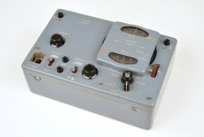
The receiver covers 2 to 12 MHz, divided over four
bands, each of which is identified with a colour. Audio is delivered
to standard USSR headphones. The antenna signal is
usually supplied via the transmitter.
The PR-56A was developed a year before the complete set,
and was also supplied separately, housed inside a small suitcase
with batteries.
➤ More about the PR-56 receiver
|
|
|
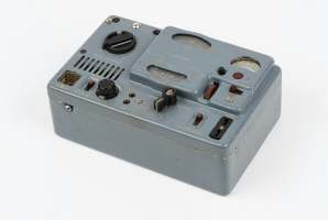
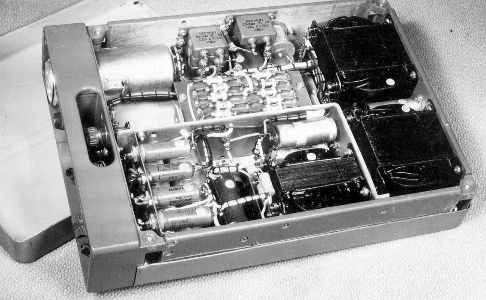
The transmitter covers 2.5 to 10 MHz – slightly less than the receiver –
divided over four bands.
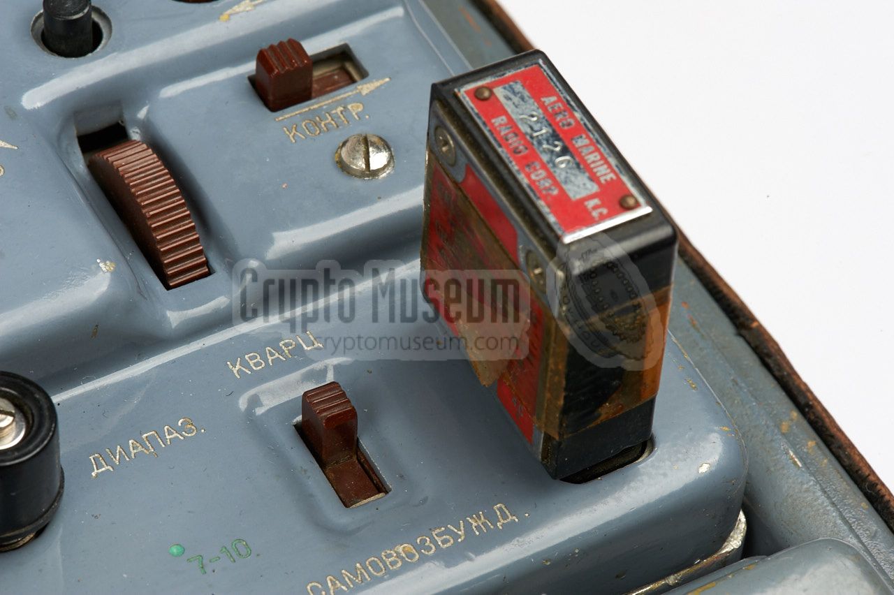
The frequency can be determined either
by a crystal, operating in the 2nd or 3rd overtone, or by the built-in
Variable Frequency Oscillator (VFO), selectable by a slide-switch. The
crystal socket is located at the front right.
➤ More about the P-57 transmitter
|
|
|
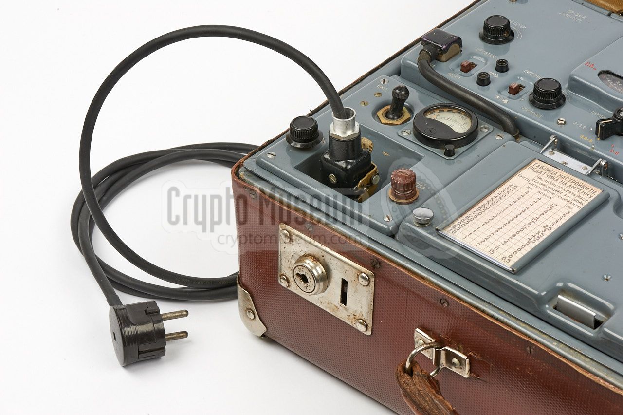
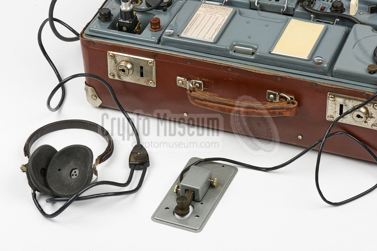
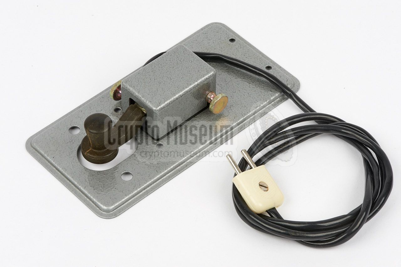
The transmitter is only suitable for transmissions in morse code (CW)
and has a small 2-pin socket at its front edge for connection of a
morse key.
RION was usually supplied with a
black miniature morse key
that fitted a slide-mount
at the center of the
lid of the large accessory compartment. In practice, most operators
used an alternative key, as the size and position of the standard one
was not very convenient. Both the original key and the slide-mount
are missing from our RION set.
|
|
|
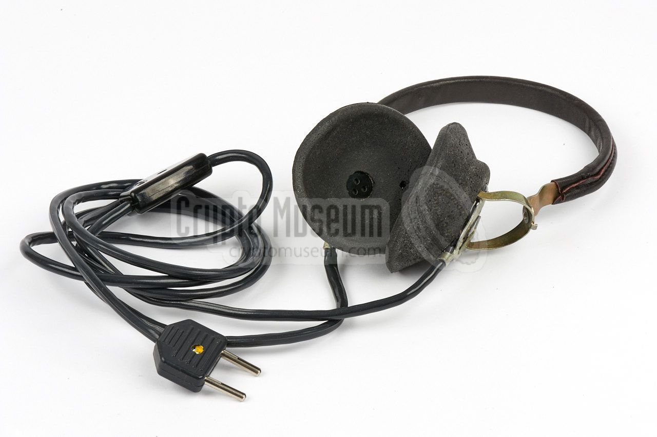
The receiver has a 2-pin socket for connection of a common pair of
headphones, such as the one shown in the image on the right. It was
supplied as a standard accessory of the RION radio set.
Alternatively, the set could also be used with a common military pair
of headphones, such as this one,
that had a canvas head band and could be stored more easily.
|
|
|
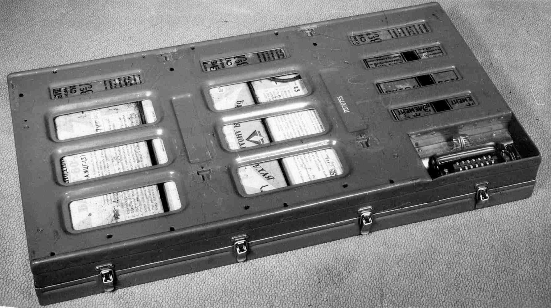
In situations where no mains network was available (e.g. in a forest),
power was provided by a large battery pack that was installed in the
empty space at the bottom of the suitcase. It was attached to the
bottom side of the hinged frame that holds the receiver and transmitter.
The battery pack consists of three 80V dry cells (BAS-G-80) connected
in series, three 1.5V cells (Z-SL-30) also connected in series, and
two 1.5V cells (Z-SL-30) connected in parallel.
➤ More
|
|
|
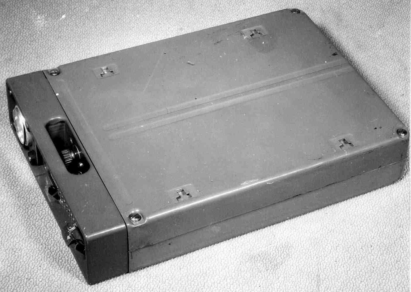
When a mains AC network was available, it was recommended to install
the (optional) power supply unit (PSU) in the bottom compartment of the
suitcase, in place of the battery pack. The PSU was normally supplied in
a separate smaller suitcase, along with the optional
power inverter.
The PSU is attached to the bottom of the hinged frame, as shown in the
image on the right, and is connected to the frame's
14-pin power plug.
|
|
|
In addition to internal batteries and the mains network, the RION set
can also be powered from an external 12V DC source, such as the battery
of a car. In that case, the optional power inverter should be installed
in the bottom section of the suitcase, replacing the battery pack.
The inverter is supplied with the PSU in a separate suitcase.
The image on the right shows the power inverter, which uses a vibrator
unit and a multi-tap transformer to convert 12V DC into the various voltages
needed for the radio set.
|
|
|
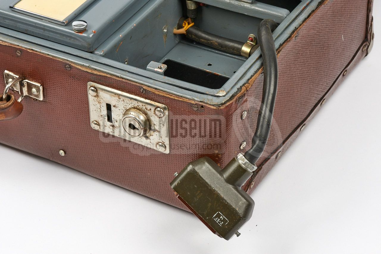
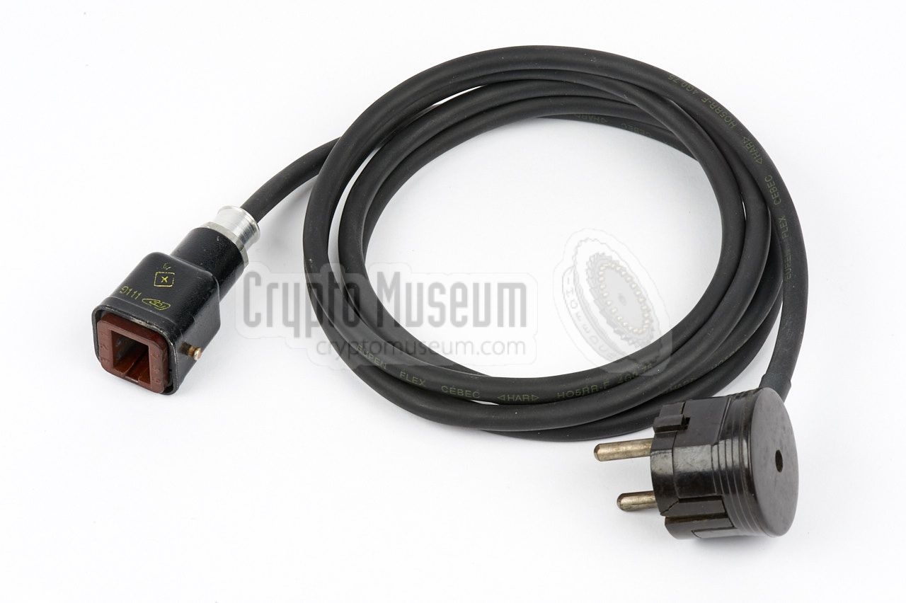
When the mains power supply unit (PSU) is installed in the lower part
of the suitcase, the radio set can be powered from the Mains AC network.
In that case, the mains power cord shown in the image on the right,
should be connected to the square 6-pin power socket at the front right
of the set.
The power plug is a common WWII German Luftwaffe connector, made by List
and several other manufacturers, and copied in the USSR. The
pinout is available below.
|
|
|
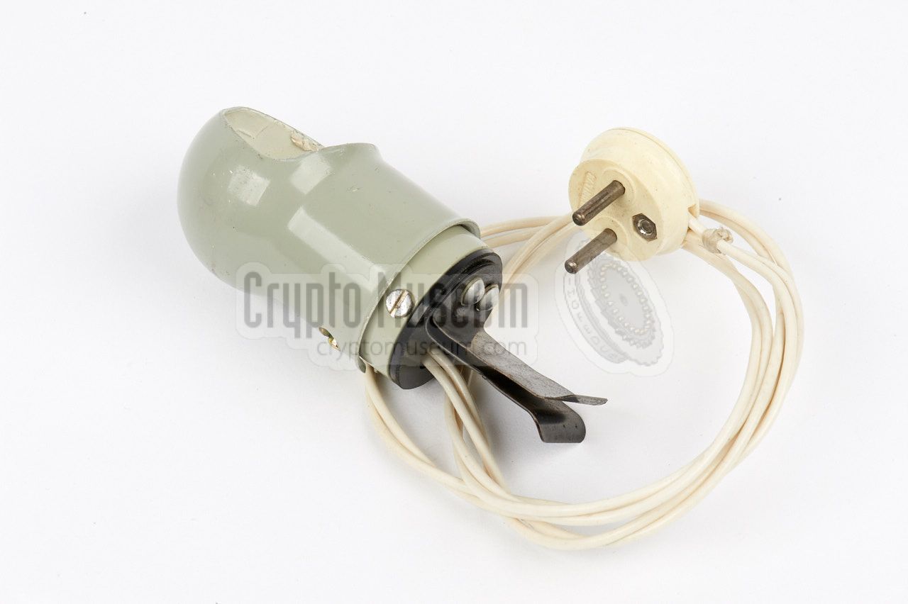
The radio set was commonly supplied with a small work lamp that could
be connected to the 2-pin socket between receiver and transmitter. This
socket provides a voltage of 4.5V and is intended to power a small 6V lamp,
with just enough light to read the frequency scales.
The lamp shown in the image on the right is not the original one that was
supplied with the radio set, but a suitable replacement. The black clip
at the bottom allows the lamp to be affixed to the top lid of the suitcase.
|
|
|
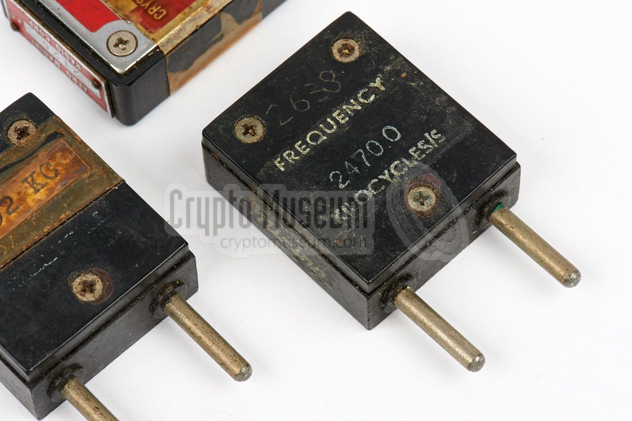
Although the transmitter can operate on any frequency within its
range, it was usually operated with crystals as they are far more
accurate and stable as the internal VFO.
Crystals can be used in the 2nd or 3rd overtone, and the socket
at the transmitter's front right is suitable for nearly any
type of quarz crystal that has thick pins. The image on the right
shows a few examples of crystals that have been found to work
well with RION.
|
|
|
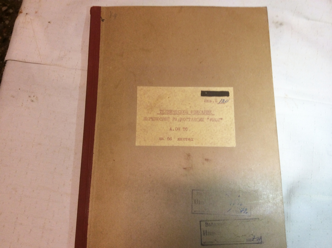
Each RION set was supplied with an operator's manual that also
contained a full technical description and circuit diagrams. The image on
the right shows an original RION manual that is stamped with the serial
number of the radio set.
The circuit diagrams are provided at the back of the manual as fold-outs.
➤ Download manual
Original technical manual. Photograph kindly supplied by ©
KGB Spy Museum [4].}
|
|
|
|
Bringing an old radio like RION back to life is always difficult.
The radio was manufactured in or around 1957 and is now nearly
70 years old. When we acquired the radio in 2017, all of the power supplies
(battery, mains PSU and inverter) were missing and the state of the
electronics inside the receiver and the transmitter was unknown,
although it appeared to be in good shape.
|
Nevertheless, it is always a good idea with any device of this age, to check
the wiring and the connections thoroughly before supplying power to it.
A first inspection learned us that the mains power switch was broken and
that some of the wiring had been modified over time. Luckily, our friends at
the KGB Spy Museum 1 in Lithuania were able to provide the original
wiring diagram.
A replacement switch was found on eBay and the original wiring was restored.
Also on eBay, we found suitable plugs an sockets for the mains connection
and for the internal power supply.
|
|
|
It was decided to build a new mains power supply unit (PSU) that could be
installed in the empty space below the radio frame. This space is normally
taken by either the battery pack, the original PSU or the inverter.
This space is approx. 5.5 cm high, which should be enough for a proper PSU.
|
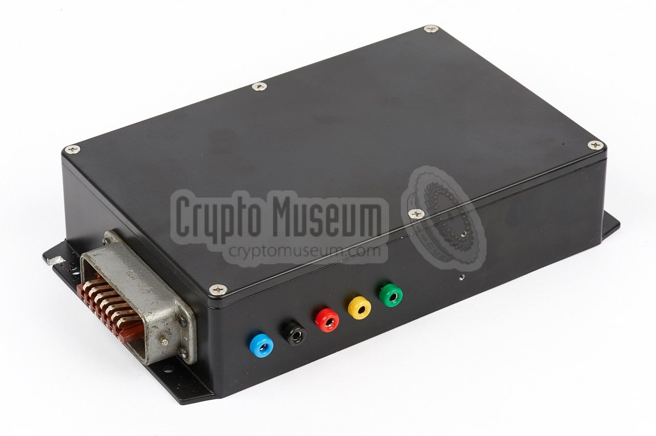
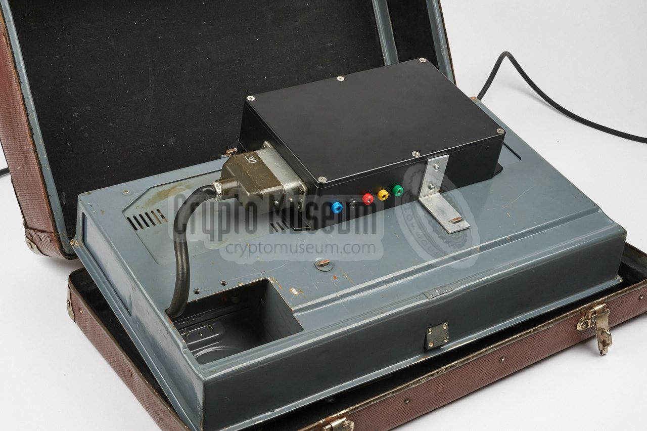
The image on the right shows the alternative PSU, which is smaller than the
original one. It is built with modern components and no attempt has been made
to make a replica of the original.
The alternative PSU is housed in a
black die-cast aluminium enclosure
that can be fitted to the bottom of the hinged frame of the radio set,
in such a position that the 14-pin socket
mates with the 14-pin plug of the existing wiring.
Inside the PSU
is a modern toroidal transformer that has been modified
for the required voltages.
|
|
|
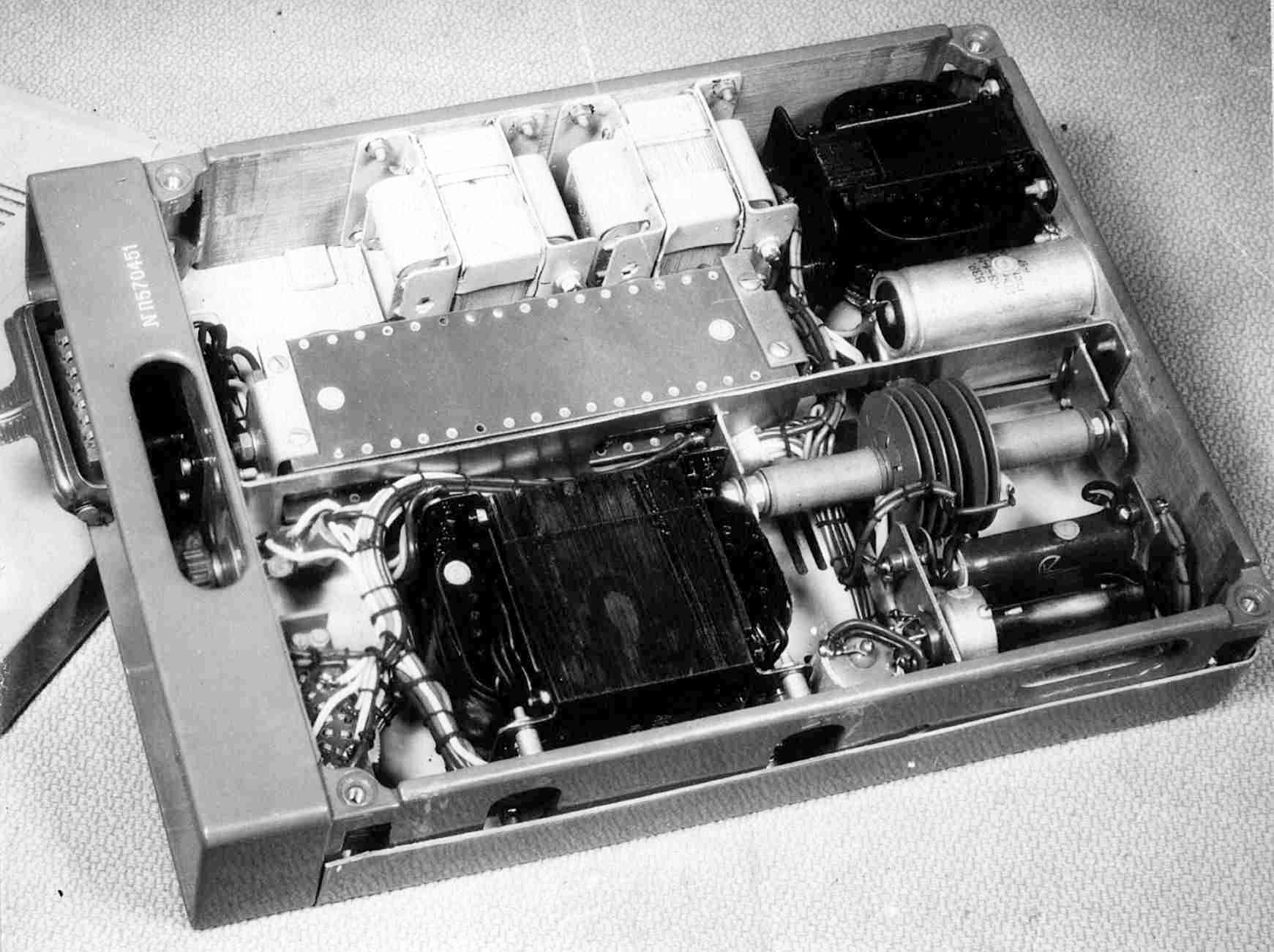
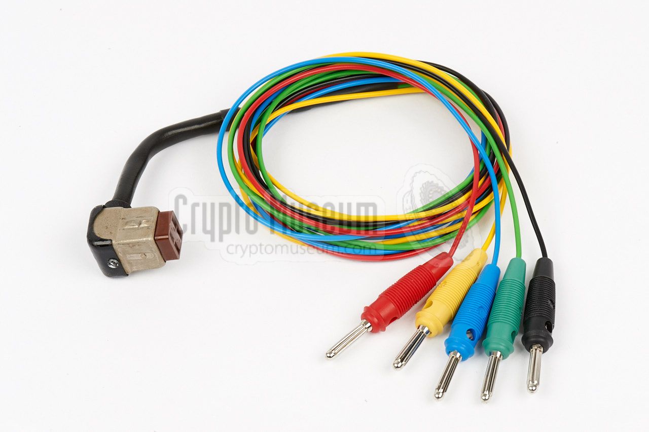
The next thing to check was the state of transmitter and receiver.
As they can both be removed from the frame easily, it was decided to test
and repair them outside the frame. We first prepaired a
universal test cable
from the short lead that came with our PR-56 receiver several years ago.
|
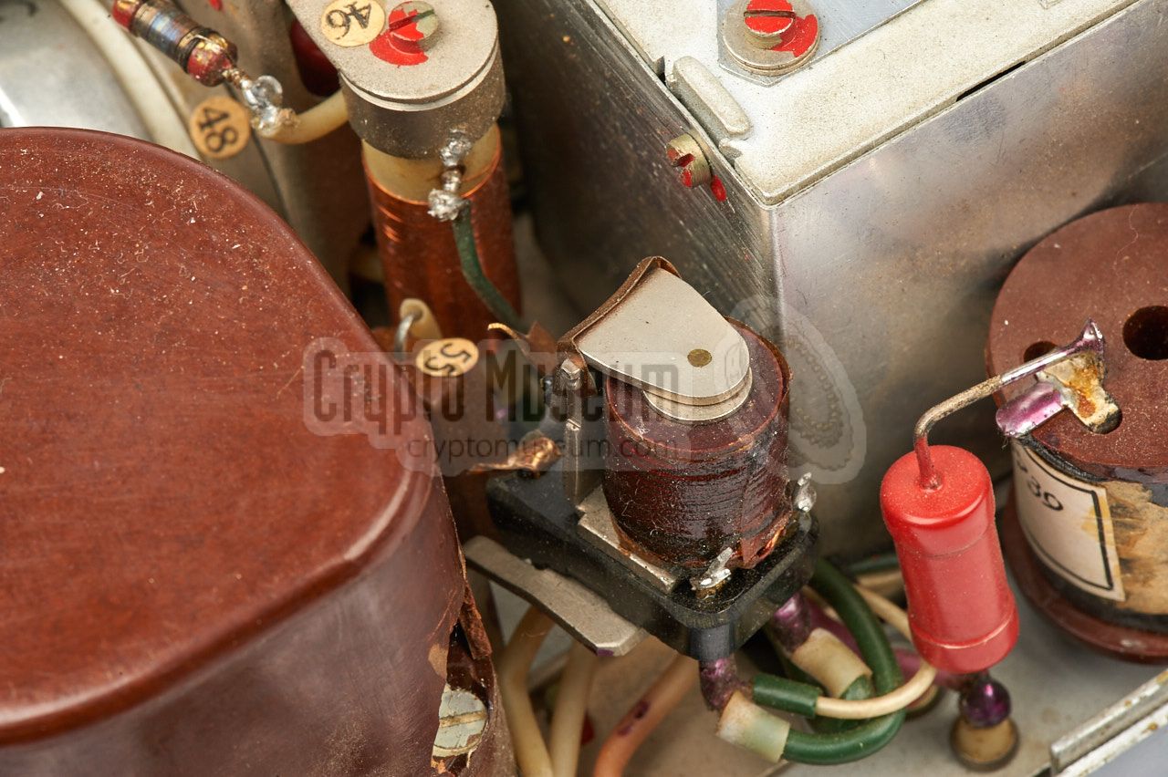
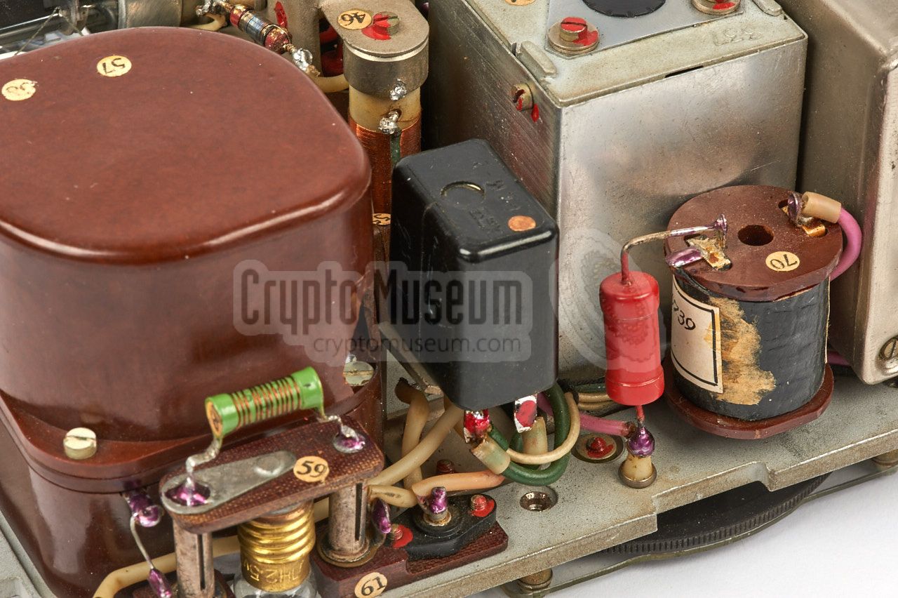
A quick inspection of the transmitter's interior learned us that it was
in good condition, but that the antenna relay was broken and that one of the
metal shields was missing. Again, our friends from the KGB Spy Museum
came to the rescue, and provided us with original replacement parts.
After replacing the broken relay
and correcting the wiring of the
transmitter's power socket, the transmitter now works again.
After connecting a wire antenna and a suitable counterpoise, the antenna
matching unit could be tuned nicely and the unit produced the expected
output power.
|
|
|
The receiver appeared to be more problematic. The first test revealed that
all seven valves were broken, probably as a result of connecting the 80V HT
voltage to the filaments. Replacement valves were ordered from several
sources on the internet and awaiting their arrival, we swapped the broken
receiver for the one we already had in our collection, which was known
to be good.
|
Now it was time to install the transmitter and the receiver in the suitcase's
frame, to see how they behave when connected to the replacement PSU via the
internal wiring. After several additional checks, main power was
switched ON and both receiver and transmitter worked immediately.
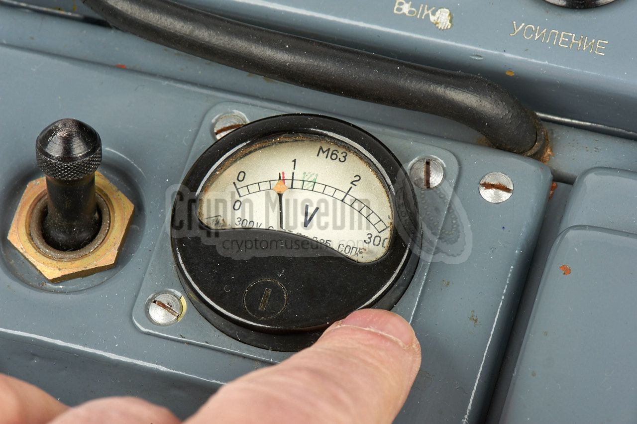
One last hickup was caused by the indicator (the 3V/300V meter)
just above the mains socket on the power module.
Although power was supplied to the panel meter, the needle
refused to move. A closer inspection revealed that the delicate instrument
inside the meter was badly corroded.
|
|
|
Luckily, we managed to take it apart,
clean it up, and re-assemble it, after which it could be used again.
Our RION spy radio set is now fully operational and can be demonstrated to
the public. Many thanks to everyone who has helped us to make
this restoration project a successful one.
|
-
KGB Spy Museum (formerly: Atomic KGB Bunker) is a Cold War museum in
Kaunas (Lithuania), housed in a cold war era atomic shelder, 6 metres
below the surface. It has several thousand items related to espionage,
war and radio, and is open to the public on special days [4].
➤ More
|
|
The following items are currently missing from our RION radio set:
|
Original headphones - Original miniature morse key
- Slide-mount for morse key
- Original work lamp
|
|
According to the original parts list, the following items should be present:
|
|
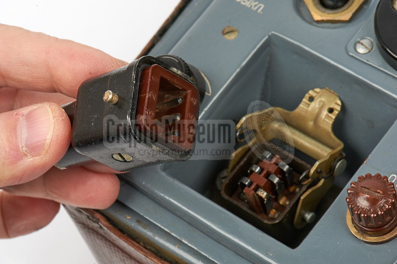
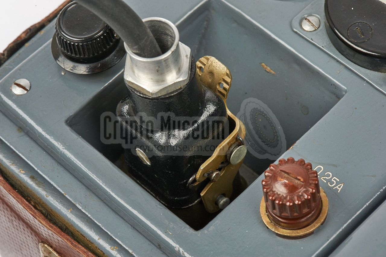
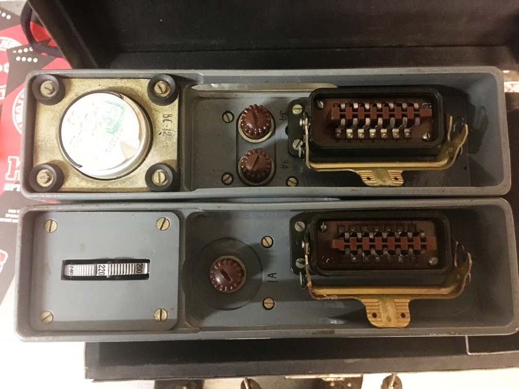
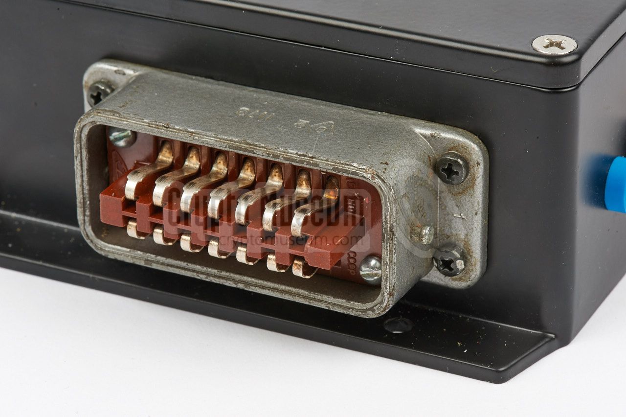
A 6-pin male socket is available for connection of the mains power cord,
at the bottom left of the control panel. This is a so-called LIST plug, or
STAF series, (now: Harting) that was used by the German Air Force (Luftwaffe)
during WWII. The plug was copied in the USSR and used for many years.
Below is the pinout of the male socket when looking into it from the control
panel. Note that, when using this connection, the internal Power Supplu Unit
(PSU) should be installed.
|
- AC Mains (~95-240V)
- AC mains (connected to 1)
- not connected
- AC Mains (~0V)
- Ground
- not connected
|
|
|
The same socket can also be used for connecting an external 12V DC power source,
such as the battery of a car. In this case, the internal Power Inverter should
be installed in the suitcase.
|
- +12V
- +12V (connected to 1)
- +4V
- not connected
- 0V (Ground)
- +2V
|
|
|
The diagrams below show the pinout of the power sockets on the PR-56A
receiver and the RION transmitter,
when looking into the socket from the front of the device.
Note that the metal shell is connected to the chassis (i.e. ground or GND).
It is used as the ground for the HT voltage (0V).
|
- LT in (+1.2V)
- LT out (switched)
- G (-4.5V)
- HT (+75V)
|
|
Note that some receivers have a different wiring of this connector.
This is the case, for example, with the PR-56A. Furthermore, in some
devices the wiring of pins 1 and 2 have erroneously been swapped. Although
this does not affect the operation of the device, it means that the
filaments are powered permanently. Also remember that some devices may have
been amateurised.
Always check the wiring before connecting the PR-56 to a power source.
If the receiver is to be used as part of the RION suitcase (i.e. installed
in the metal frame), you may have to correct some of the wiring.
In this case, use the internal wiring diagram
and the battery wiring scheme below.
|
- LT (-4.5V)
- not connected
- LT (0V)
- HT (270V)
|
|
|
RION is powered by a dry-cell battery pack, a power inverter
or a mains PSU, one of which can be fitted inside the bottom compartment
of the suitcase.
A 14-pin female LIST plug in the cable compartment at the front right is
present for connection to the batteries or the power inverter.
The diagram below shows the pinout when looking into the female socket
on the cable end.
|
- AC Mains 0V (from P1-4)
- Ground
- Ground
- not connected
- LT 3V max
- Fuse
- RX LT 0V
- AC mains
- not connected
- Looped to 8 (AC mains)
- TX LT in
- TX LT 0V (from P1-3)
- not connected
- HT
|
|
Below is the wiring diagram of the hinged metal frame that holds the individual
components. The wiring diagram is based on the drawings in the technical manual
[A] and has been verified against an actual RION radio set. Please note that
in practice, variations or modifications are possible. Do not rely on this
diagram, but verify it before applying power to the set. Most of the components
in the diagram below, are mounted to the rear of the power unit at the front
left of the radio set.
The 6-pin socket at the left is the mains power input that is located on the front
left of the radio set. It is connected to the large 14-pin plug to which the
abtteries, the PSU or the power inverter should be connected. In turn, the 14-pin
plug provides power to the receiver and the transmitter.
|
The battery pack should be connected to the large 14-pin plug
that resides in the empty space below the hinged frame, at the bottom of the
suitcase. The diagram below shows how it is wired.
Three 80V dry batteries (BAS-G-80) are connected in series, to provide
+240V for the transmitter. It has a tap after the first battery, that provides
+80V for the receiver. At the top are three 1.5V batteries (Z-SL-30) connected
in series to provide the +4.5V LT voltage for the filaments of the transmitter.
These batteries are also used to provide the -4.5V grid voltage for the receiver.
Two further 1.5V batteries are connected in parallel to provide the 1.2V for the
receiver's filaments.
The above diagram can also be used as a guide for the wiring of the PSU,
or when creating a replacement PSU, in which case the mains AC voltage will
be available at pins 1 and 8 of the 14-pin plug. The correct AC mains voltage
should be selected on the voltage caroussel of the PSU.
|
- scAvenger, Technical description of the RION spy set
Website with many photographs. Riga, Latvia.
21 January 2005. Retrieved October 2009. 1
- Louis Meulstee, Wireless for the Warrior, volume 4
ISBN 0952063-36-0, September 2004. 2
- Radio Scanner, Radio Station 'RION'
Website (Russian). Retrieved May 2016.
- Julius Urbaitis, KGB Spy Museum
Personal correspondence, February 2017.
|
-
Website no longer available in 2016.
-
In this book the receiver is erroneously called GR-56A.
|
|
|
|
Any links shown in red are currently unavailable.
If you like the information on this website, why not make a donation?
© Crypto Museum. Created: Thursday 01 October 2009. Last changed: Monday, 22 January 2024 - 15:57 CET.
|
 |

|
|
|


