|
|
|
|
|

|
|
← USA CIA Cold War SF
|
|
RS-69
AN/PRC-64 (Delco 5300)
|
|
|
USA Spy Radio Set
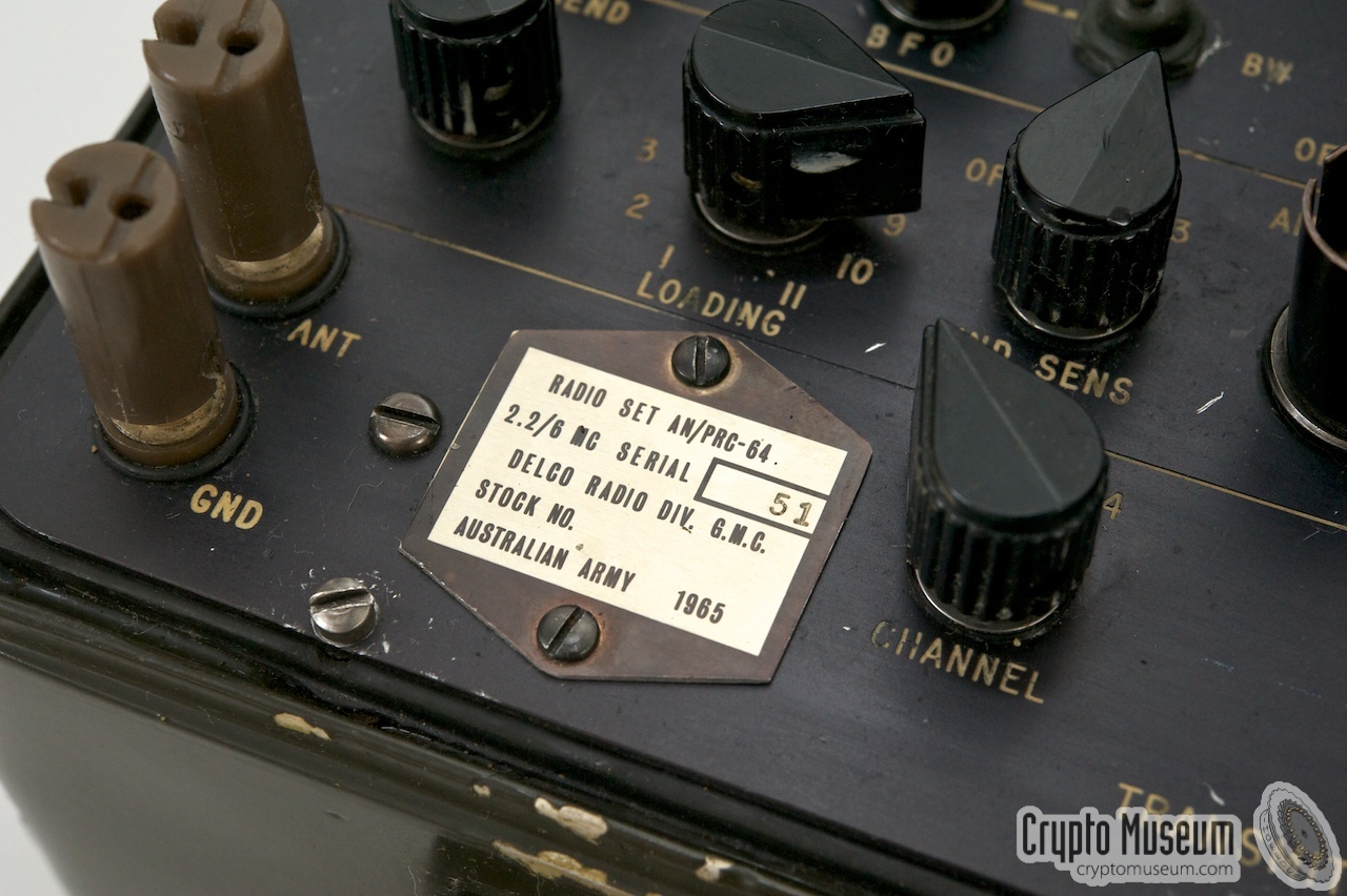
AN/PRC-64 (later: RS-69) was a miliature paramilitary
spy radio set, developed in the early 1960s
by Delco in the USA,
as a possible successor to the
RS-1 (AN/GRC-109).
It was intended for agente communication and for paramilitary use
by Special Forces (SF).
The (black) CIA version is also known as Delco 5300.
The set is known to have been used by the Special Operations Group of the
Australian Army in Vietnam, and its featured in Keith Melton's book
Ultimate Spy [4].
|
During their operational life, most of the PRC-64 units were upgraded to
PRC-64A, which allowed faster burst transmissions in combination
with the AN/GRA-71 burst encoder
(see below) that was connected to the 7-pin morse KEY socket.
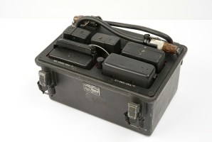
The image on the right shows a typical PRC-64A radio set with the
main accessories connected. Apart from the sweet little bakelite
morse key, an even smaller key is present
on the radio itself.
Contary to other spy sets of the same era, the PRC-64 was also
suitable for voice transmission, hence the presence of a dynamic
microphone.
|
|
|
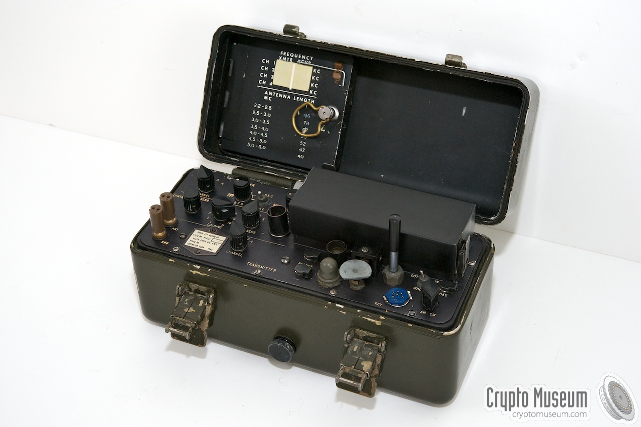
Frequency selection of the PRC-64 is crystal controlled, limiting
its operation to 4 preset channels. Receiver and transmitter each have
their own set of 4 crystals to allow split-frequency operation.
The frequency range is from 2.2 to 6.0 MHz.
RX and TX frequencies are usually written in a table inside the top lid.
The crystals were stored in a compartment behind the table.
The PRC-64 is powered by an internal battery and is switched
on by opening the top lid.
It was an extremely compact unit for its time and measures
only 25 x 13 x 12 cm. Even when packed with the accessories
in the canvas carrying bag, it measures less than 35 x 14
x 14 cm and weights less than 3.5 kg including the battery.
The small size comes at a price however, as the HF output power
is no more than 5 Watt (CW morse) or 1.5 Watt (AM voice).
The radio was used for several decades as indicated by the
date code on a #morse)
that was found recently (1986).
|
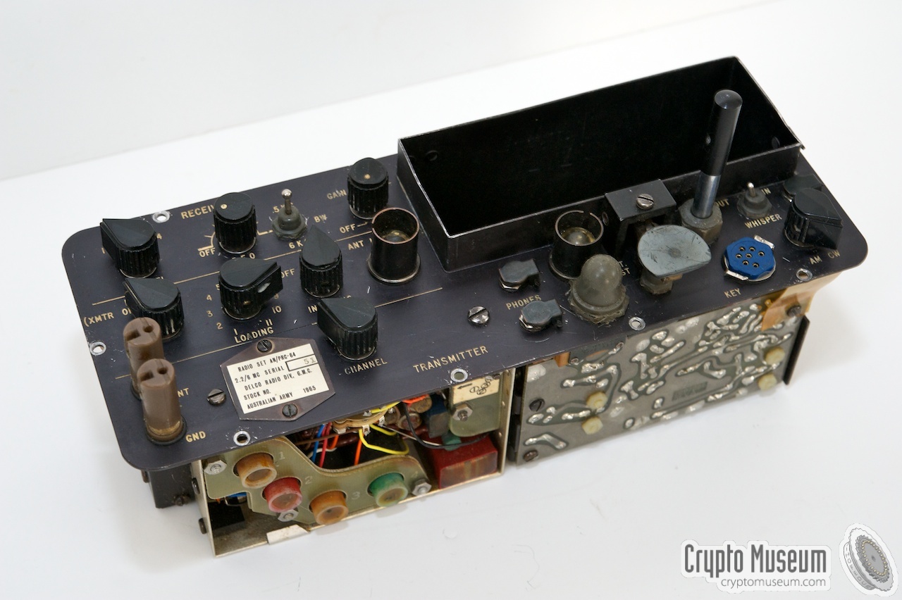
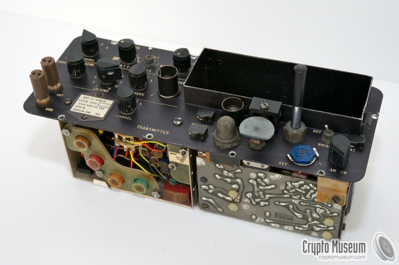
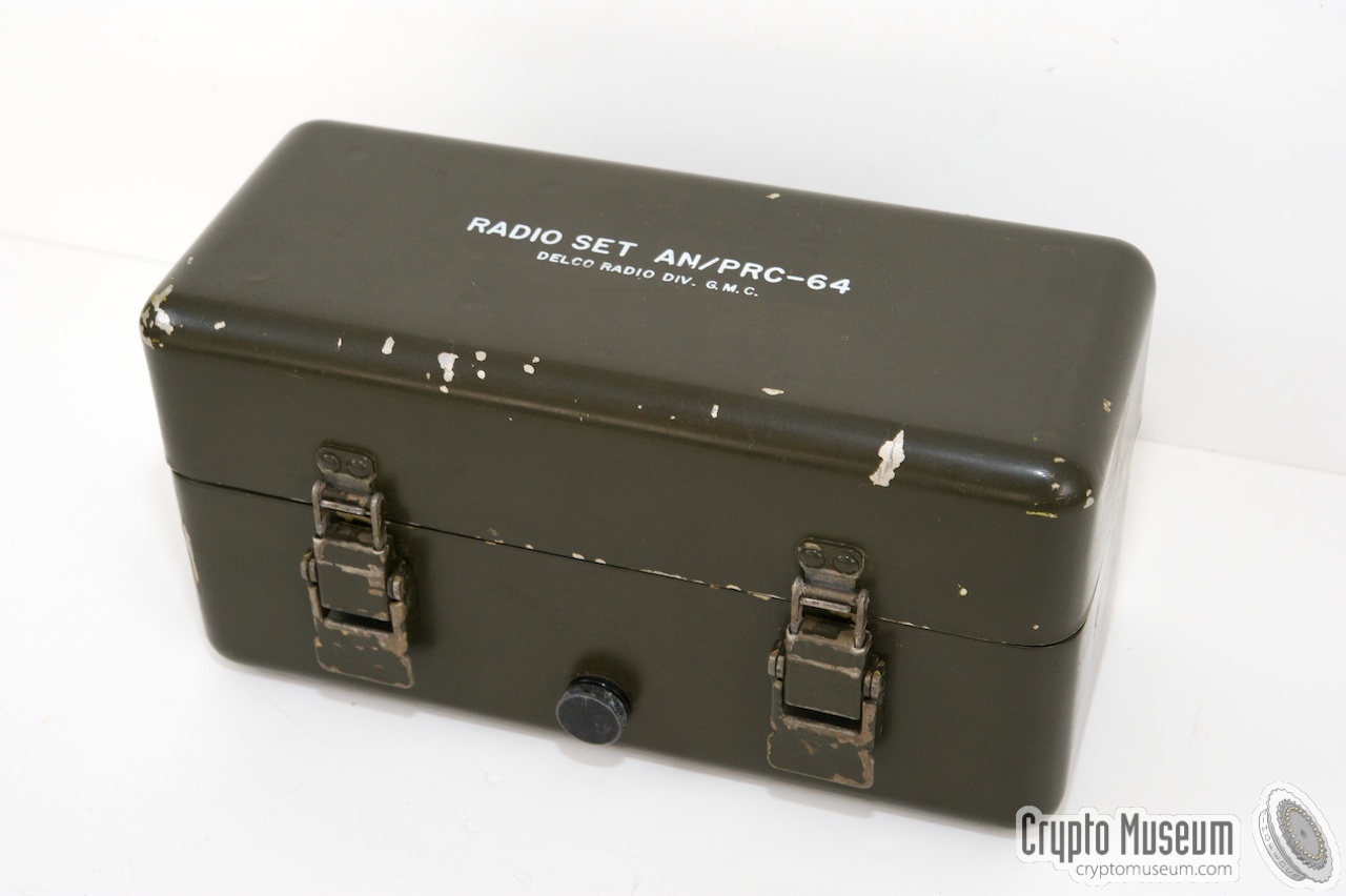
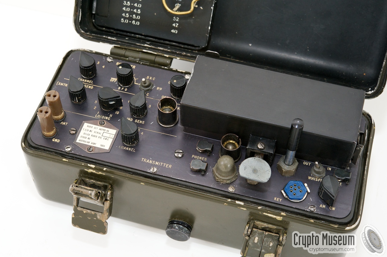
The entire PRC-64 radio is no larger than an average lunchbox.
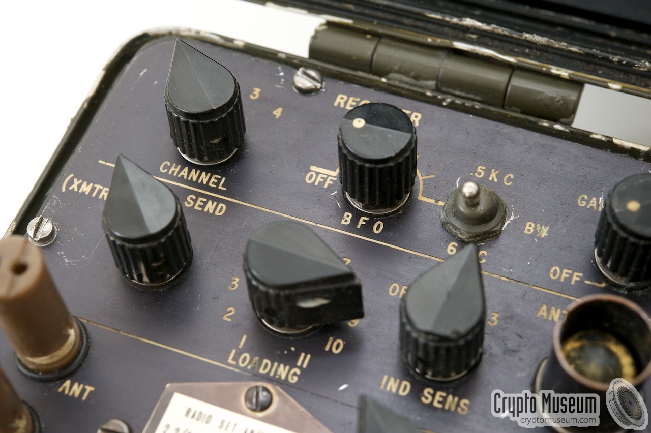
Opening the top lid, reveals the control panel where all switches
and adjustments are nicely arranged. The front panel can be roughly divided
into four sections: the receiver (top left), the transmitter (bottom left),
the battery (top right) and the input/output section (modulator, bottom right).
The battery compartment accepts a BA-1509/PRC-64 battery that supplies
three voltages: +4V, +12V and +28V. These batteries were purpose-built for
this radio and are no longer available. Earphone(s) and microphone are
connected at the bottom right, where also the blue socket for an external
key or burst keyer is located. The RX and TX channels can be selected
independently, but is limited to just 4 channels each. For this, suitable
crystals have to be inserted inside the radio.
Compared to earlier spy radio set, the built-in Antenna Tuner has
a limited range, increasing the importance of the correct antenna (wire)
length.
Note that the channel selectors also act as a Frequency Range (BAND)
selector, limiting the range for each channel as follows:
|
Delco 5300
- 3.0 - 3.9 MHz
- 3.8 - 4.9 MHz
- 4.8 - 6.3 MHz
- 6.2 - 8.0 MHz
|
|
|
PRC-64
- 4.6 - 6 MHz
- 2.3 - 2.85 MHz
- 2.8 - 3.65 MHz
- 3.6 - 4.7 MHz
|
|
The PRC-64 was derived from the Delco 5300 radio that was built
especially for use by the CIA. The Delco 5300 is physically identical,
but has a black case, rather than green, and has a different
frequency range (3.0 to 8.0 MHz).
Furthermore, some of the controls on the front panel
are red rather than black.
At the moment we don't have a picture of the Delco 5300 available.
|
- Delco 5300
Frequency range: 3 - 8 MHz. No 0.5/6kHz bandwidth switch.
This is the original version of the radio, that was used by the CIA
for clandestine operations. The internal morse key is a true
(adjustable) telegraph key rather than a microswitch (see below).
- Delco 5300A
Same as the above, but with 0.5/6kHz bandwidth switch for the receiver.
- PRC-64
Frequency range 2.2 - 6 MHz. This is the Army variant of the Delco 5300.
The 0.5/6kHz bandwidth switch is available on the receiver and the radio
has a simpler battery-test circuit (24V only). Furthermore, the transmitter
uses a larger crystal (CR-89) and the morse key has been simplified
(microswitch). Probably developed around 1964.
- PRC-64A
Same as the PRC-64 above, but modified for use in combination with a
high-speed burst keyer. The modification consists of a daughter board on
the transmitter module and was probably issued around 1968.
|
|
From Ray Robinson in Australia [1],
we received two photographs of Delco 5300 sets.
One is a plain Delco 5300
as used by the CIA for clandestine
operations, and the other one is a
Delco 5300C.
The latter is shown in the image on the right.
|
|
|
During the early 1970's, John Trist from Deniliquin (Australia) was
a so-called Patrol Sig. He was trained on the AN/PRC-64 for 6½ weeks
before being deployed to the Jungle, using the 64 Set as a lifeline
from places like Borneo, Malaya and Vietnam.
In 2014, John Trist looked back on his days in active service and wrote
an article for the Australian Branch of the Royal Naval Amateur Radio
Society, in which he gives a account of the operation of the
AN/PRC-64 in the jungle [3].
➤ Read the full article
|
|
|
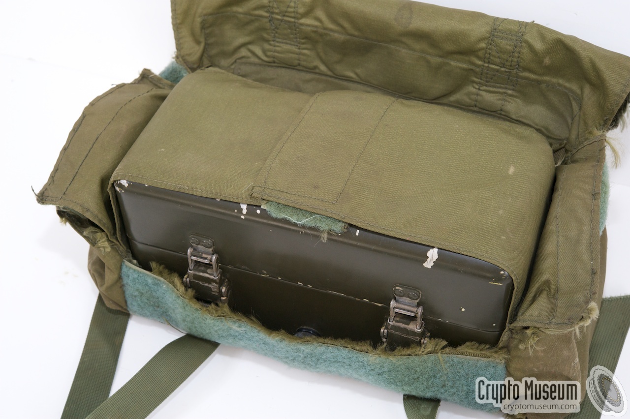
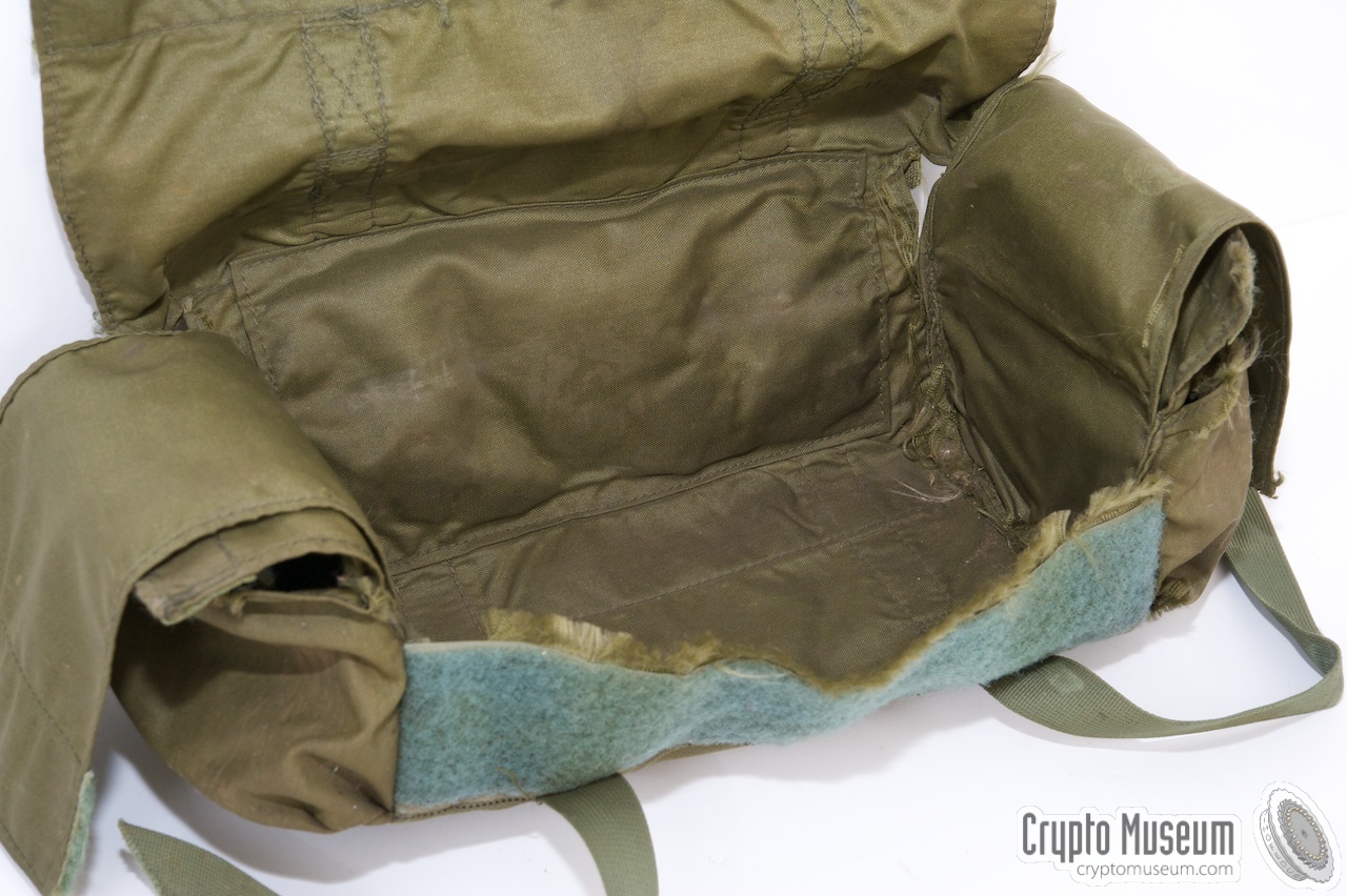
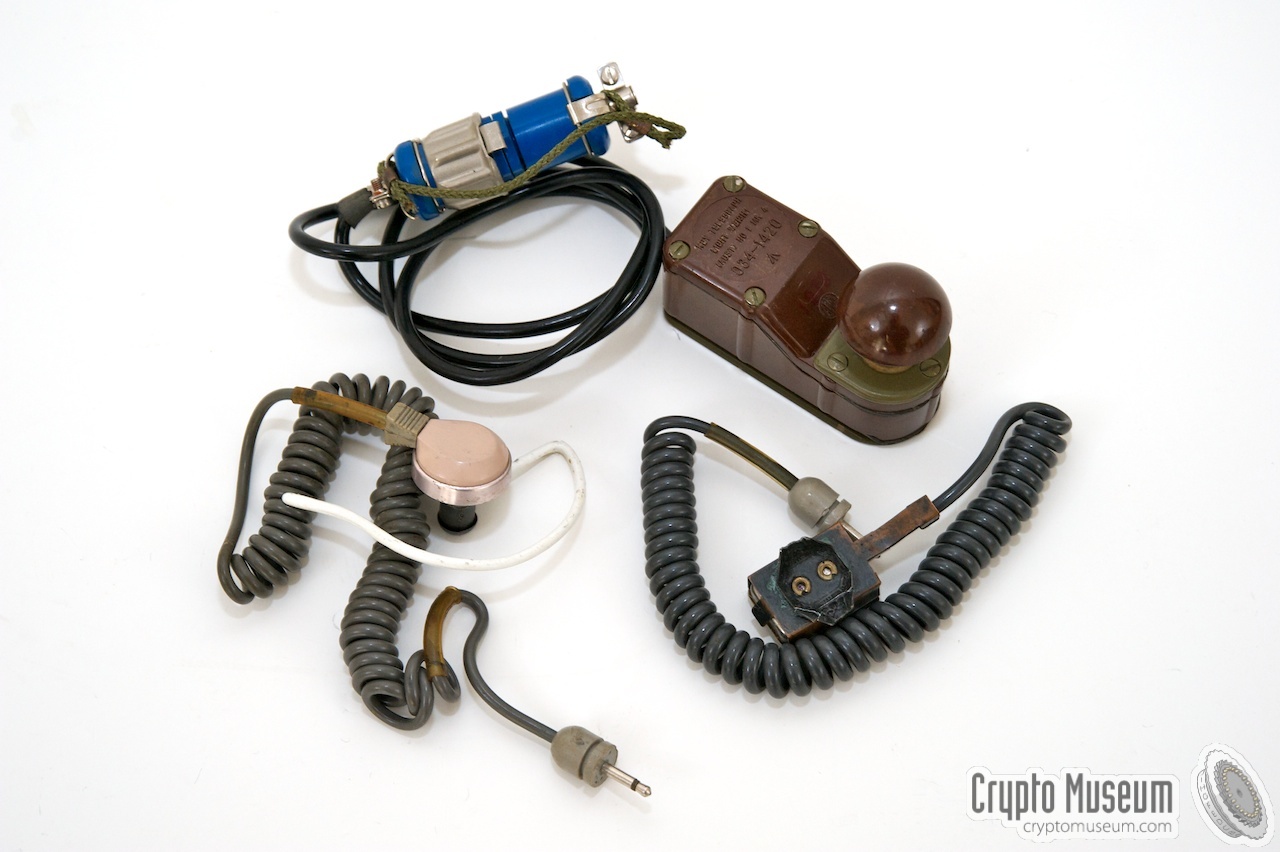
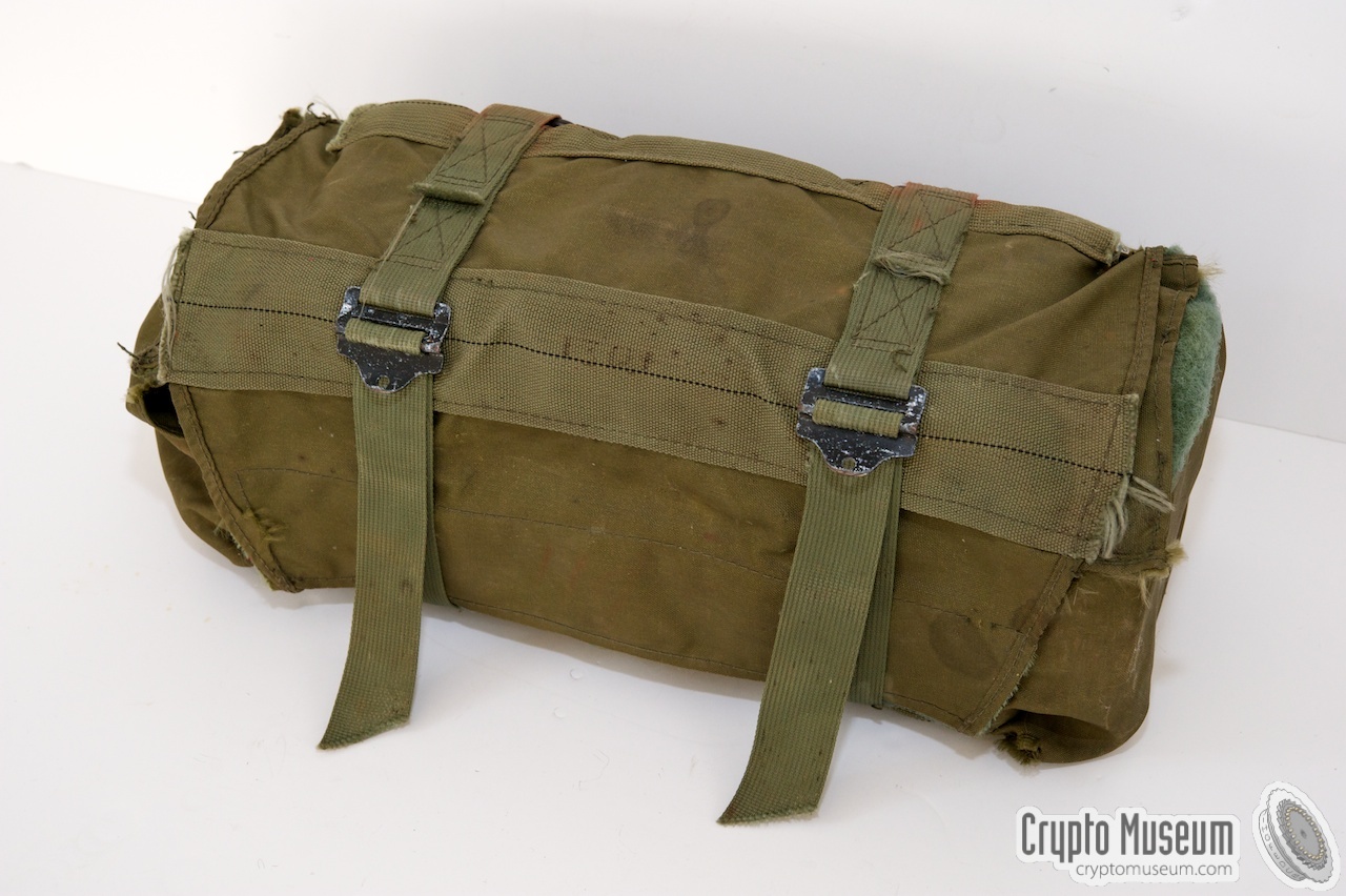
When unused, the PRC-64 is normally stored inside a small rugged
canvas bag, together with the main accessories, such as microphone,
ear pieces, morse key and antennas.
The image on the right shows the canvas bag with the PRC-64 radio
at the center. Two small pockets - one at either side of the bag -
are used to store the accessories.
Microphone, ear pieces and morse key are
stored in one pocket, whilst the antenna reels
are stored in the other one.
|
|
|
|
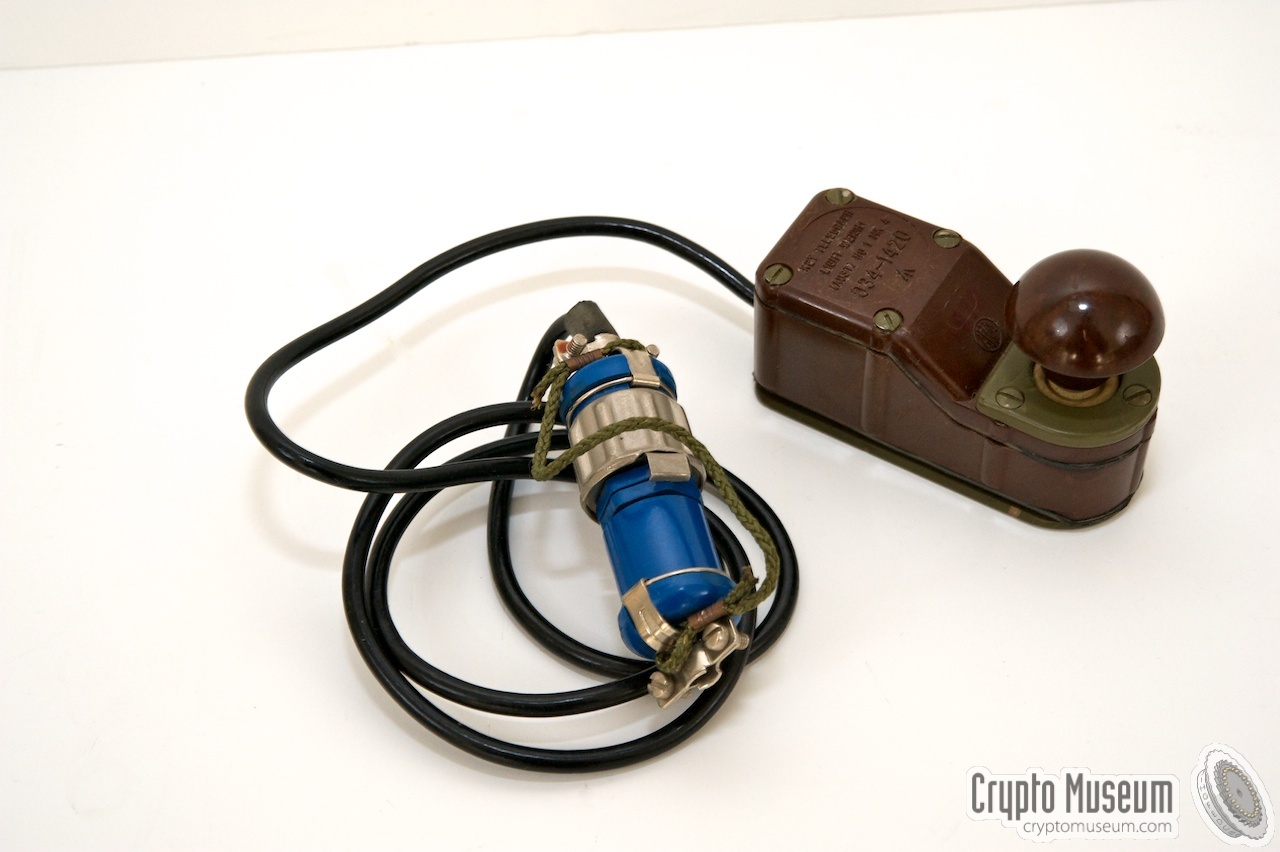
For sending messages in morse code,
the PRC-64 is usually operated with an external morse key
that is connected to the blue KEY socket
at the bottom right of the radio's control panel.
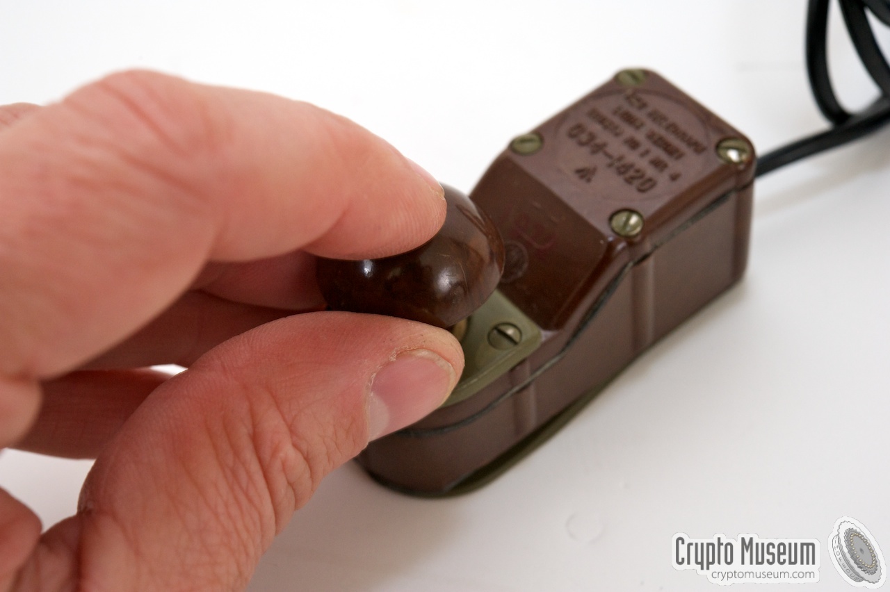
For this purpose, the radio was supplied with
a small bakelite morse key,
which has a short piece of cable (50 cm) with
a 7-pin connector at the end.
The socket is also used for an external burst encoder.
|
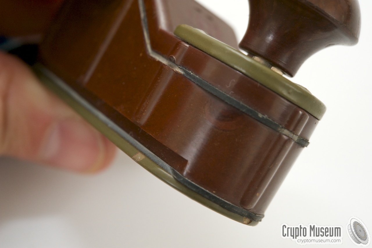
The morse key is also known by its National Stock Number
NSN 5805 66 034 1420 and was available until at least 1986.
A recently found spare key (Mark 4 variant) was dated 26
September 1986. This means that the radio set itself was
probably still in use at that time.
For emergency purposes, the PRC-64 also has a tiny little
internal morse key on its front panel.
It is located to the left of the KEY socket. It has a flattened side
to allow the case lid to pass by.
|
|
|
|
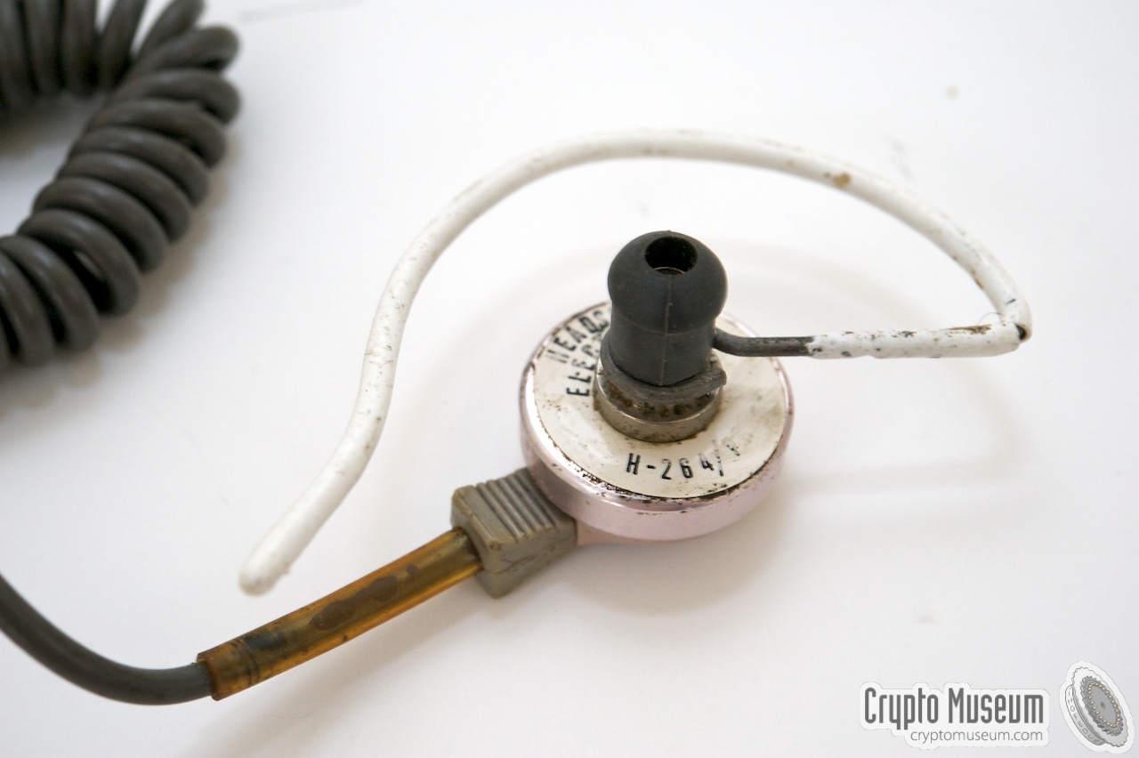
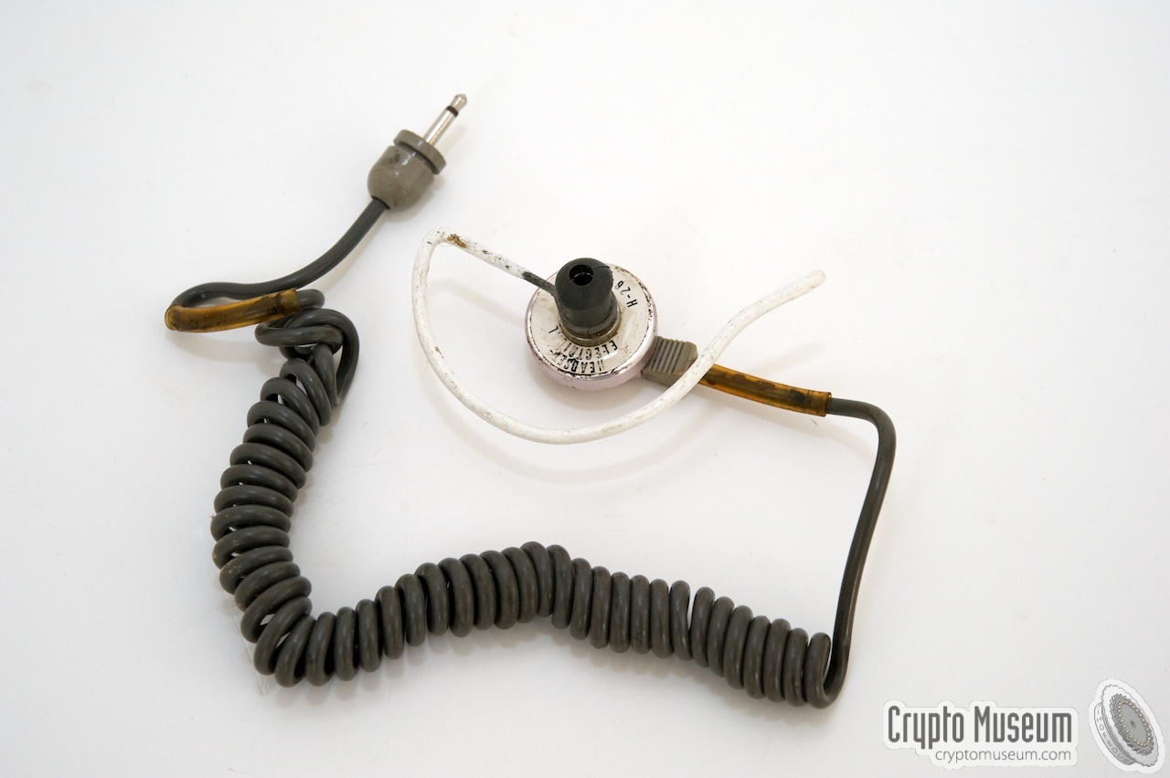
The PRC-64 was usually supplied with two ear pieces; one
for each ear. It also allowed a second person to listen
to the incoming message. At the center of the front panel
are two PHONE sockets.
|
|
|
|
Unlike most other spy sets of the same era, the PRC-64 can
also be used for the transmission of voice messages.
A small dynamic microphone is supplied,
which connects to a socket at the far right of the front panel.
When used for speech, the mode-selector has to be set to AM.
|
|
|
|
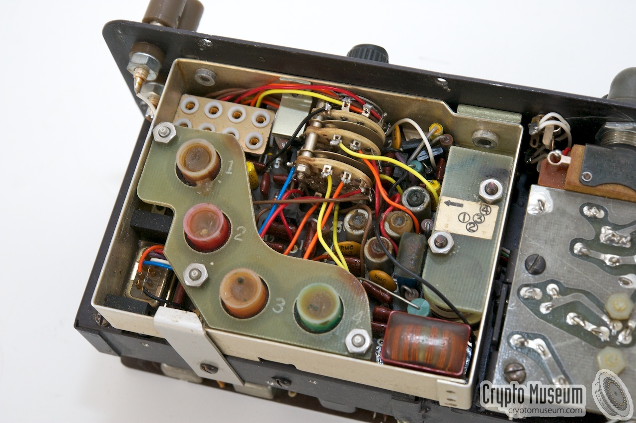
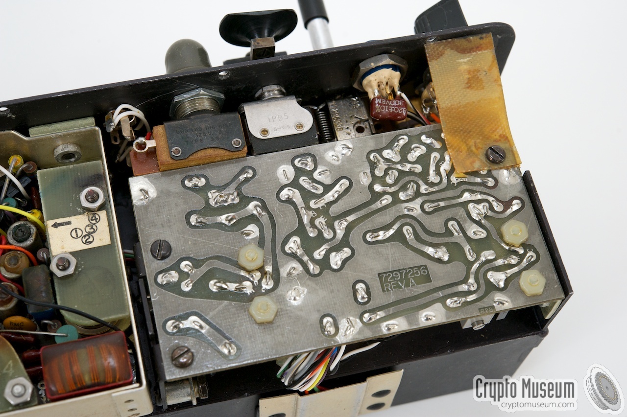
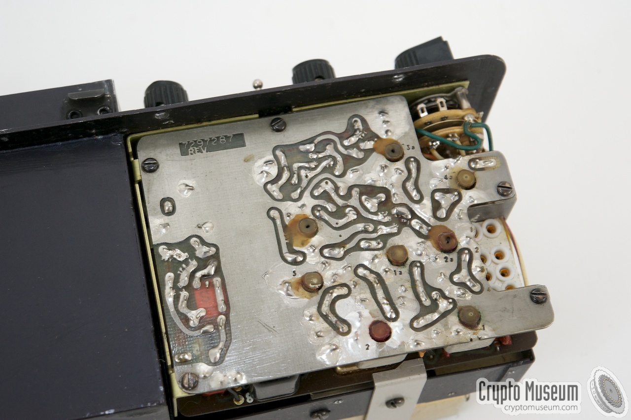
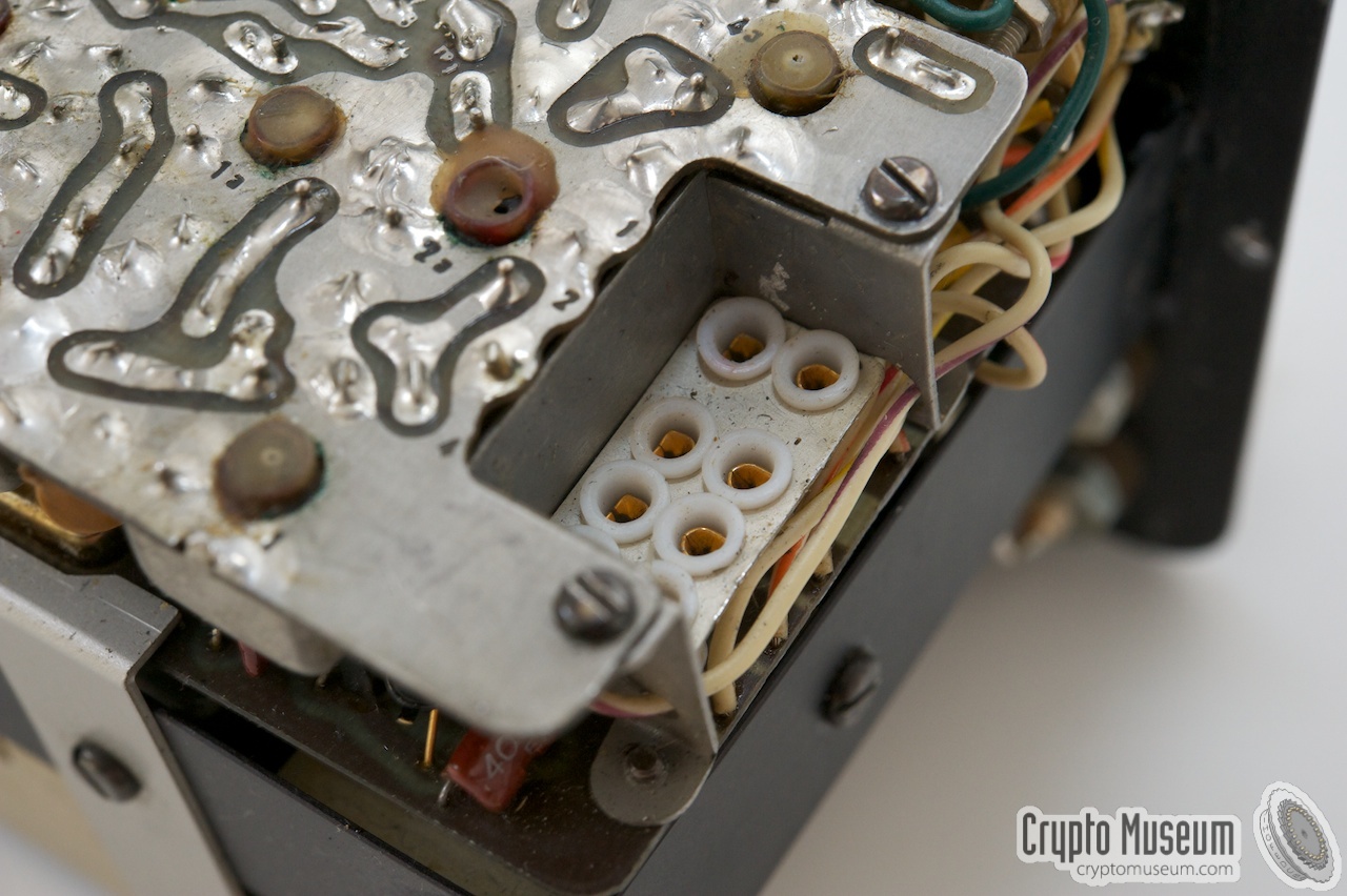
Due to the modular construction of the PRC-64, the radio is easily
serviceable. After removing 10 bolts around the edges of the front
panel, the entire radio can be taken out of the case.
|
As the entire radio is bolted to the front panel, and all controls
and connections are on the front panel, the radio can be operated
outside the case. After removing the knobs and some bolts from the
front panel, each module can be removed easily.
Some modules, such as the receiver, can even be operated when removed,
by using an extension cable, making it easier to adjust it.
|
|
|
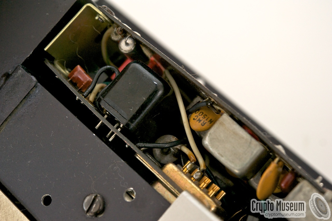
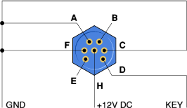
An external telegraph key can be connected to the 7-pin Winchester M7S
socket that is present to the right of the internal morse key. The same
socket can be used to connect an external Burst Encoder
such as the AN/GRA-71. The pinout
of this socket is compatible with the the KE-8B Keyer (KY-468) that is
part of the GRA-71 kit. The internal wiring of this socket is as follows:
An external key should be connected between the KEY input and GND (pins
D and F). A +12V power source is provided by the PRC-64A for the external
(burst) keyer (pin H), using GND for the negative terminal (pins A, C and F).
When using a 5-way 1-to-1 cable, the KE-8B Keyer of the GRA-71 can be used
directly with the PRC-64A. Pins B and E are not used at either end.
|
|
|
|
Any links shown in red are currently unavailable.
If you like the information on this website, why not make a donation?
© Crypto Museum. Created: Saturday 29 September 2012. Last changed: Tuesday, 25 April 2023 - 07:15 CET.
|
 |

|
|
|


![Delco 5300C. Copyright Ray Robinson [4].](img/delco_5300c_1.jpg)
![Delco 5300C. Copyright Ray Robinson [4].](img/delco_5300c_1_thumb.jpg "image # delco_5300c_1.jpg")
![Standard Delco 5300. Unknown author [5].](img/delco_5300_1.jpg)