|
|
|
|
|

|
|
Rotor Enigma Steckern UKW-D Uhr M3 → ← D
The Service Enigma Machine
Enigma I (Roman '1') is an
electromechanical cipher machine
developed in 1927/29 by Chriffriermaschinen AG
(later: Heimsoeth und Rinke)
In Berlin (Germany) for the German Army (Reichswehr, later: Wehrmacht) 1
and introduced in 1930.
It is based on the chassis of
commercial Enigma K, but has a fixed
reflector and a plugboard (Steckerbrett) at the front.
The plugboard was exclusive to the German Armed Forces.
The machine was used throughout WWII and is known under various names.
It is officially known as Enigma I
and by its factory designators: Ch.11a and Ch.11f.
|
The machine was initially supplied with three cipher wheels (rotors),
that could be inserted in 6 possible orders (3 x 2 x 1).
In December 1938, two additional rotors were supplied,
bringing the total number of possible rotor orders to 60 (5 x 4 x 3) —
a 10-fold security improvement.
It is the Steckerbrett however that has the largest impact on the total
number of combnations.
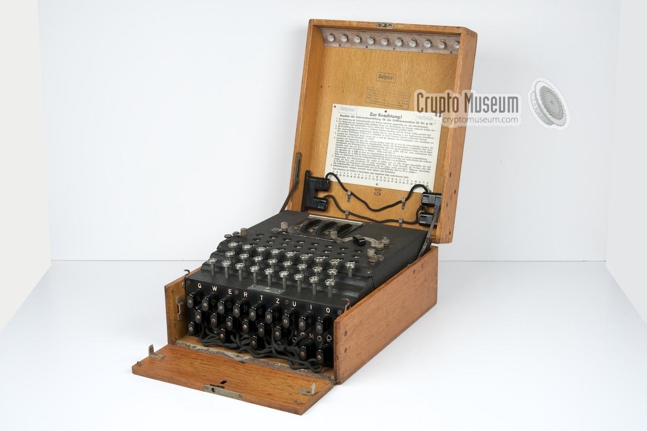
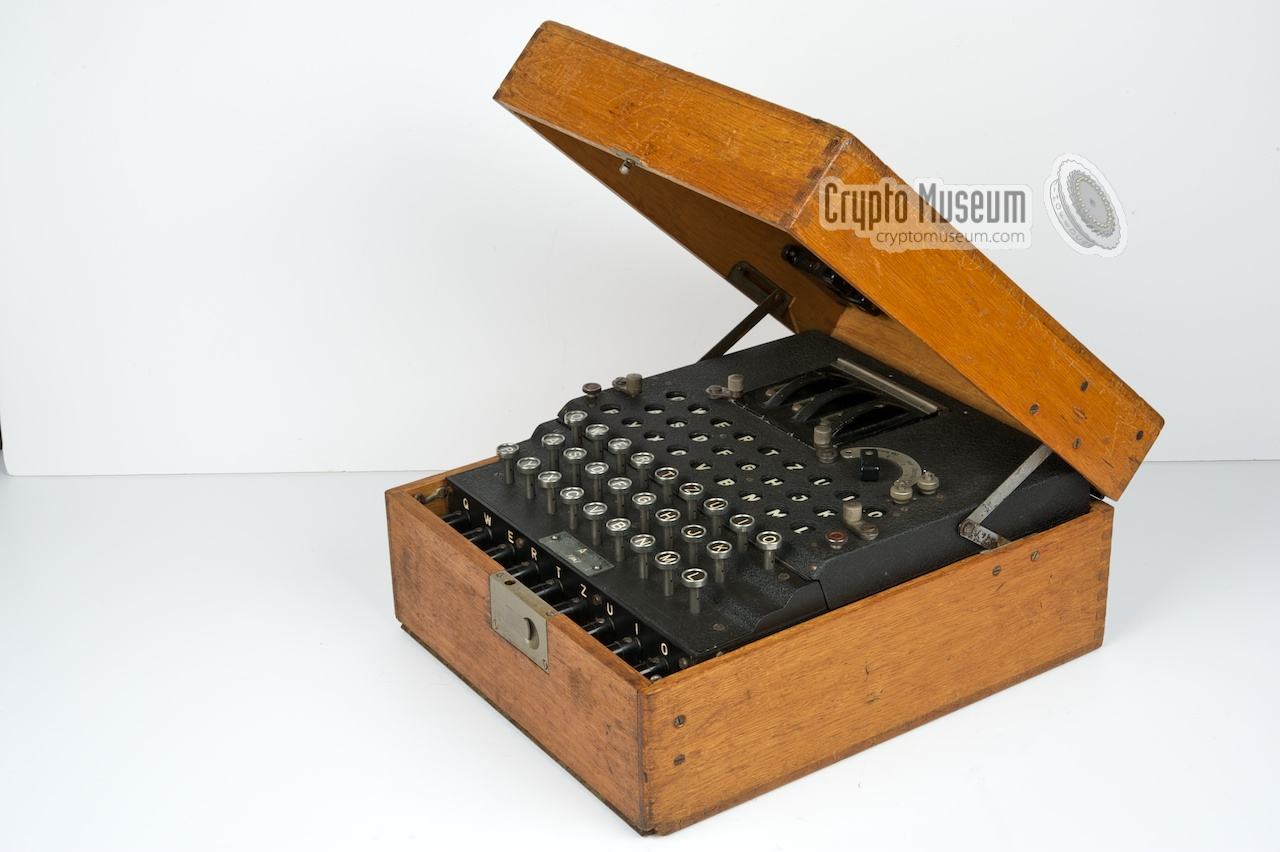
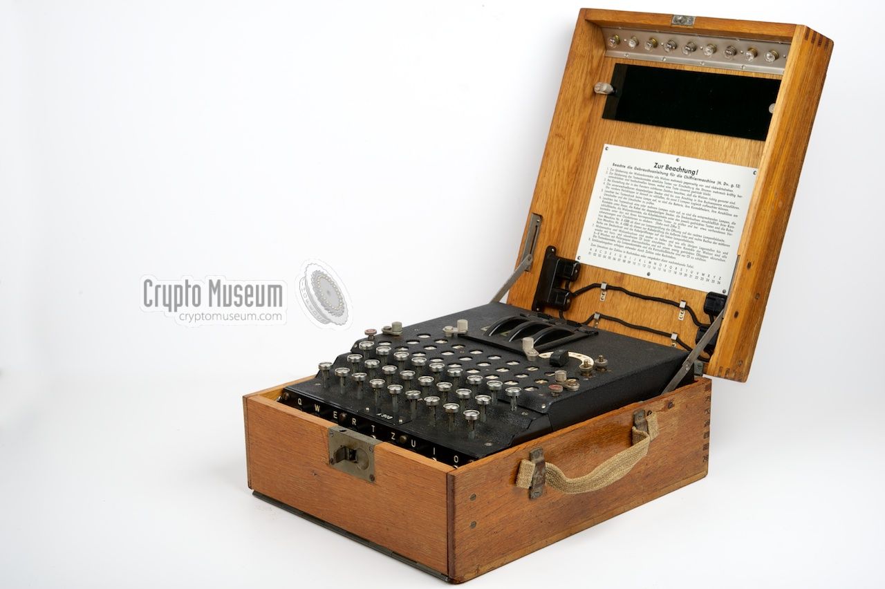
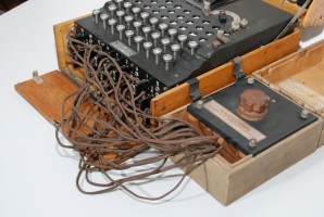
The image on the right shows a typical Enigma I that was used by the
German Army. It was found as lost luggage in a train in Italy at the
end of WWII, and is shown here with open top lid and flap.
|
|
|
The Enigma I was used by both the Heer (Army) and the
Luftwaffe (Air Force).
It was later also adopted by the Kriegsmarine (German Navy) where it
became known as the M1,
M2 and finally the
M3.
The only obvious differency between the Army version and the
Navy version is that the rotors of the latter have letters (A-Z)
rather than numbers.
About 20,000 machines of this type were manufactured by
various manufacturers,
but only several hundreds have survived.
|
-
The Reichswehr was the German Army of the so-called Weimar Republic,
from 1921 to 1935. In 1935 it was converted to the Wehrmacht (1935-1946).
➤ Wikipedia
|
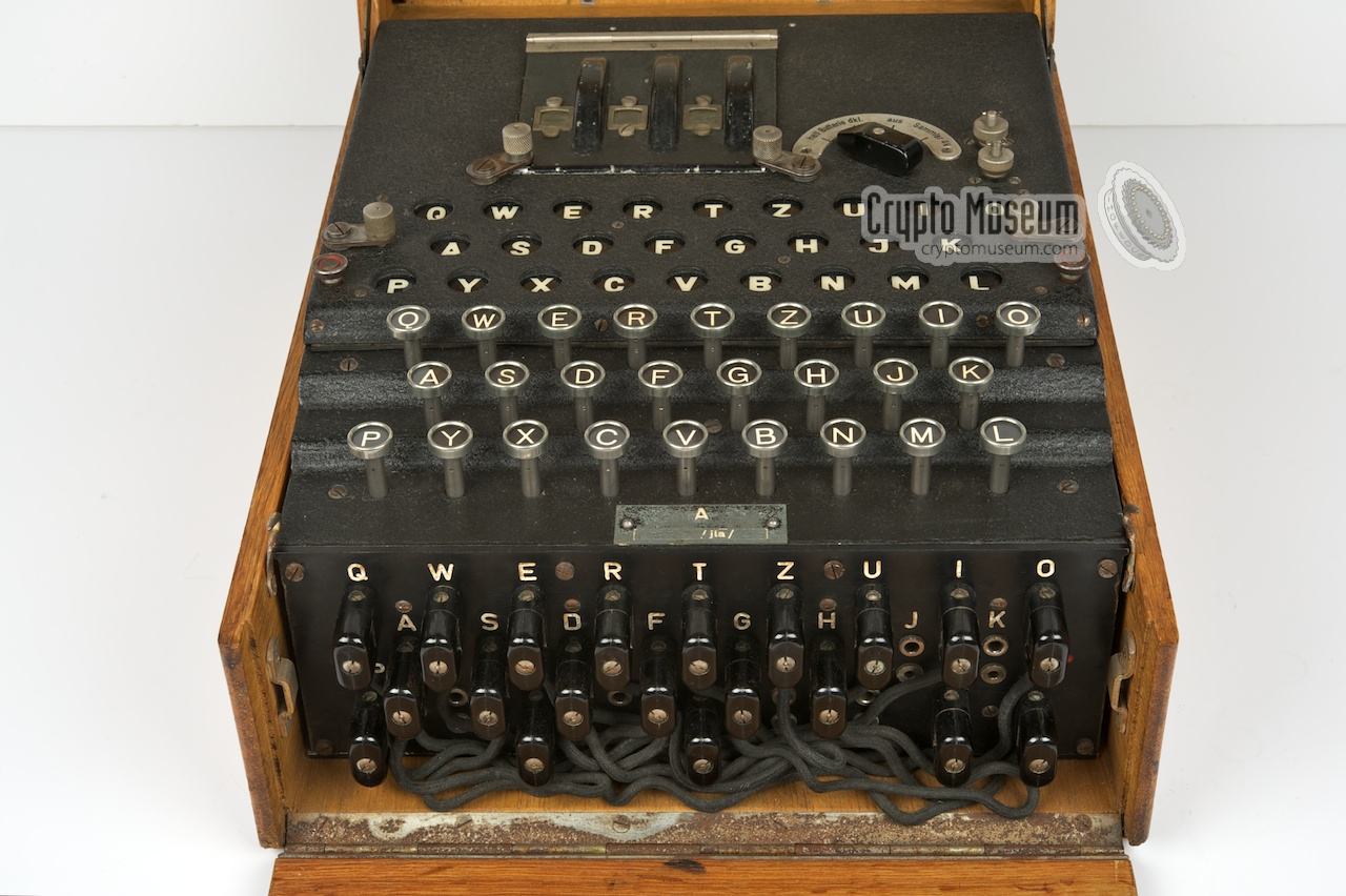
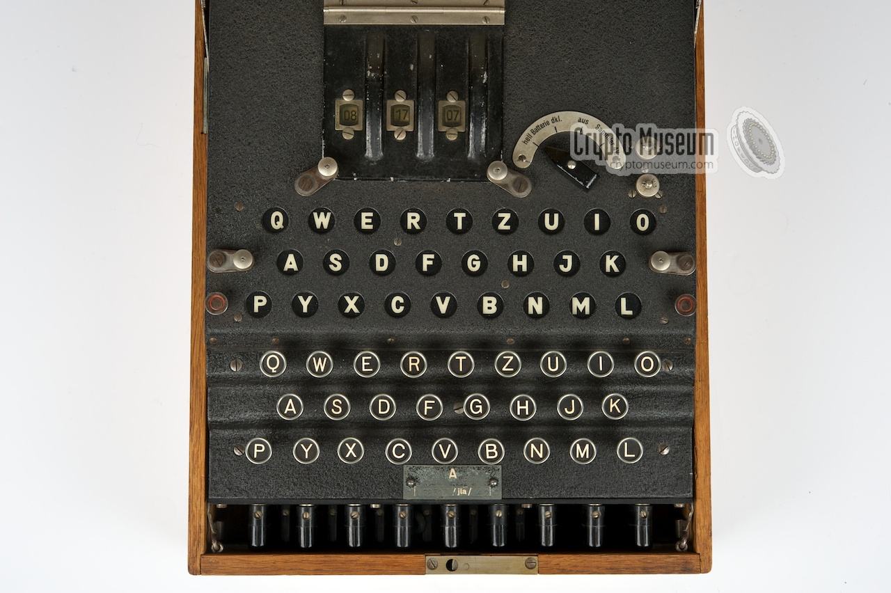
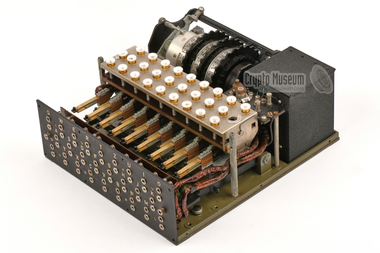
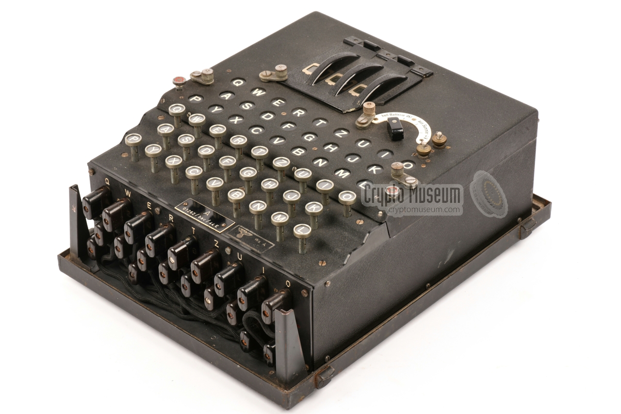
The diagram below shows the various features of the Enigma I. The machine
is shown here with the top lid and the front flap open, ready for use.
The machine is powered by a 4.5V battery and is turned on with the
large rotary switch
to the right of the cipher rotors. To the right of this switch
are two screw terminals that allow the machine to be powered by an external
source.
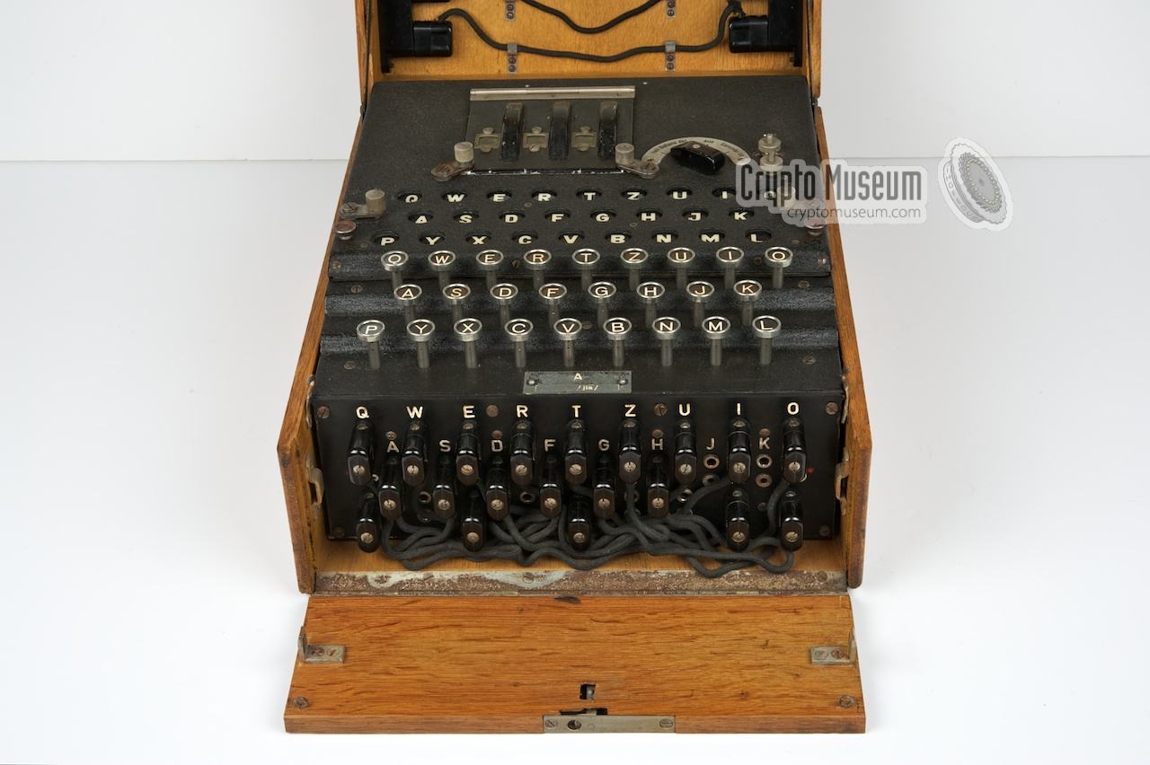
The machine has three electromechanical cipher rotors (selected from a
set of 5 rotors),
each with 26 contacts at either side. The layout of the
keyboard and the lamp panel
is in the standard QWERTZ order. As the Enigma I
is a military machine, it has a plugboard at the front,
covered by a wooden
flap that has to be closed during operation to ensure that all plugs are
fully inserted.
|
Below is the simplyfied circuit diagram of the Enigma I.
At the right is the keyboard and the lamp panel. At the far right is
the battery. When a key is pressed, the current flows from the battery
through one of the switches (i.e. a letter key), the Steckerbrett
and the cipher rotors, until it hits the reflector at the left.
The current is then returned through the rotors and the Steckerbrett
after which a lamp is lit.
In the example below, the letter 'Q' is pressed after which the
'E' lights up.
|
| |
Simplified circuit diagram of a 3-rotor Service Enigma
|
Each time a key is pressed, the rightmost rotor makes a single step
which effectively alters the wiring of that rotor. After the rotor has
made a full revolution, it will cause the rotor to its left to make a
single step, much like an odometer in a car. In the following description
it is assumed that you are familiar with the operating principle
of the Enigma. If you are not, click here.
➤ Enigma working principle
|
A great animation on how the Enigma works is available below.
It was created in December 2021 by Jared Owen, and features Enigma I —
the most common Enigma model that was used by the German Army during
WWII. For more great
animations, visit Jared Owen's YouTube channel [3].
|
In 1926, the German Army — at the time known as the Reichswehr — adopted the
lamp-based Enigma machine, or Glühlampenmaschine as it was then called.
In early 1927, the first machine with a
single-ended Steckerbrett (plug board)
was developed. Each letter of the alphabet could be
transposed to any other letter. It can be seen as the equivalent of a
freely rewirable rotor that does not move.
Experiments showed however that it was too easy to make mistakes with them.
Later that year the final version,
with an improved double-ended Steckerbrett was released.
It was based on the chassis of the Enigma D
and was given the internal designator Ch. 11a.
The first batch of machines (approx. 600 units) were delivered on
10 December 1927. This version of the machine was known by the Reichswehr
as Enigma I (Roman number 1).
All further German Army Enigma machines that were built before and
during the war, would be based on the Ch.11a.
➤ Full history
The photograph above shows an Enigma machine in operation, and was
probably taken inside a radio van during WWII. The image was
scanned from an extremely small 27 x 38 mm original and was digitally
cleaned up and enhanced.
More wartime Enigma photographs
are available here...
|
|
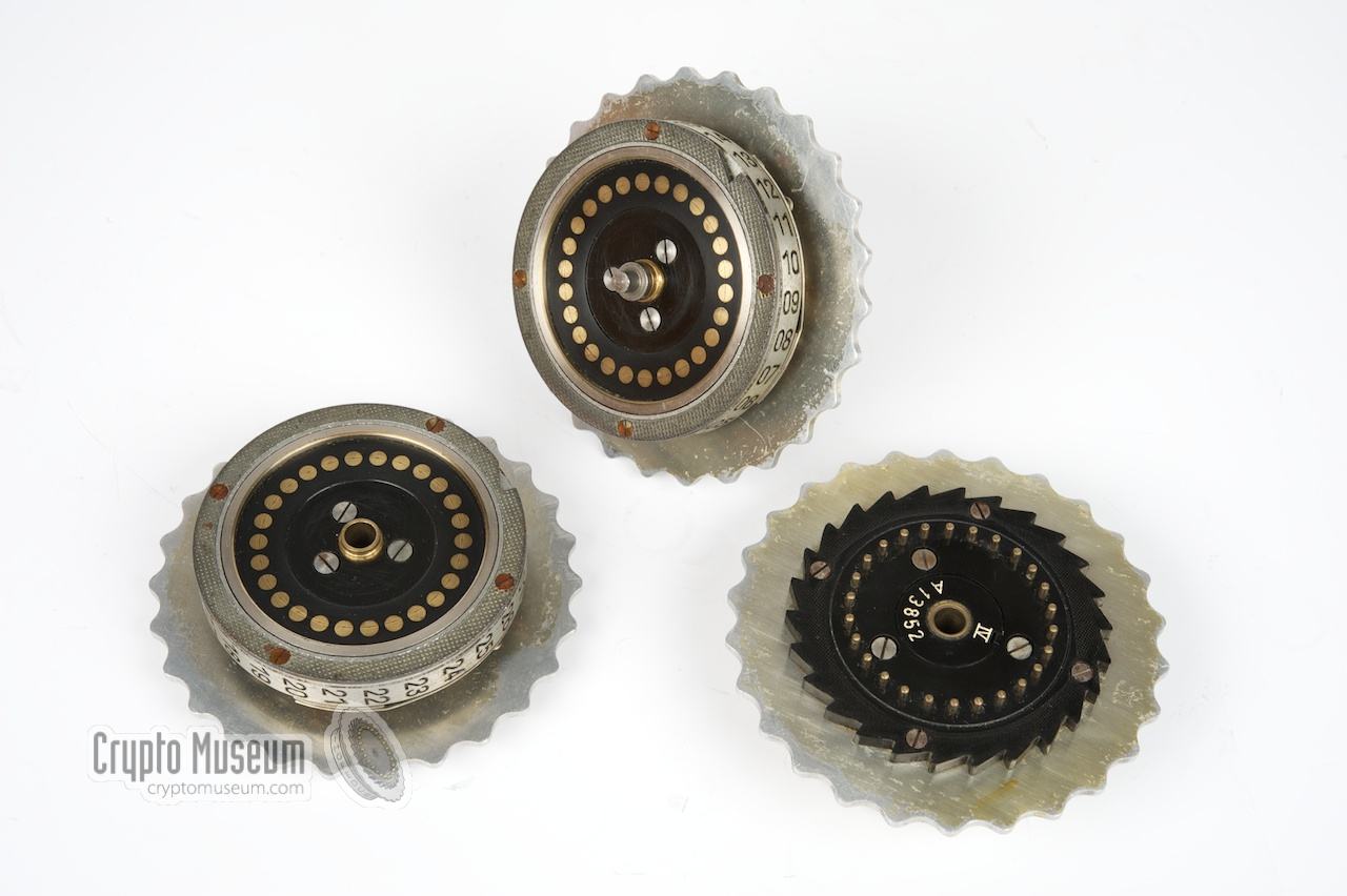
From 15 December 1938 onwards, each Enigma I was supplied with five
cipher rotors instead of three, of which three were in the machine at any given time.
Each day, the operator would place the three chosen rotors in the machine in a particular order, as instructed by the
codebook.
|
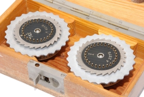
The remaining two (unused) rotors were stored in a small wooden box.
The image on the right shows a typical example of such a storage box with
the two rotors each held by a spindle.
Although other types of boxes are known to exist, this was the most
commonly used model.
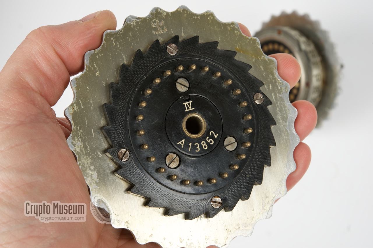
Click the image for a closer look. As you can see, rotors I and V are
currentlty stored inside the wooden box, which means that the remaining rotors
(II, III and IV) are currently fitted inside the machine. With 3 out of 5
used, the number of possible rotor orders is 5 x 4 x 3 = 60.
|
|
|
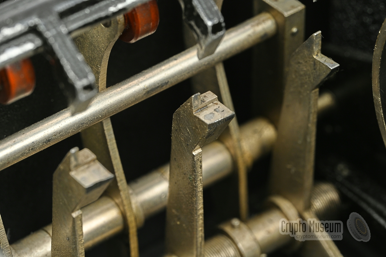
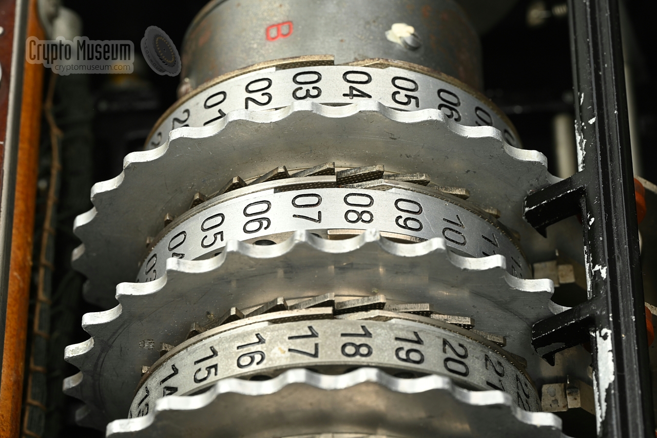
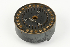
Each rotor has a single notch on its circumference. Whenever the rotor
reaches the position of the notch, a pawl is engaged. This pawl then causes
the next rotor (i.e. the rotor to the left of the current rotor) to make
a single step. This movement is called Enigma stepping.
The position of the notch is different on each rotor (see the wiring table below).
One of the disadvantages of having just one notch on each cipher rotor,
is that rotor stepping will be very regular and can therefore more easily
be predicted.
Other machines, such as the Enigma G and the
Tirpitz (Enigma T), featured multiple notches and had
therefore an irregular (less predictable) rotor motion. Such machines lacked
the additional Steckerbrett however.
|
|
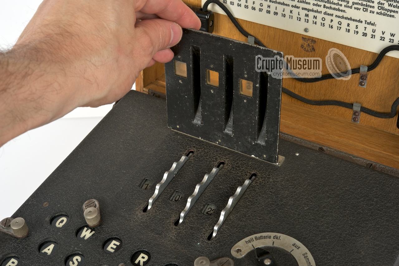
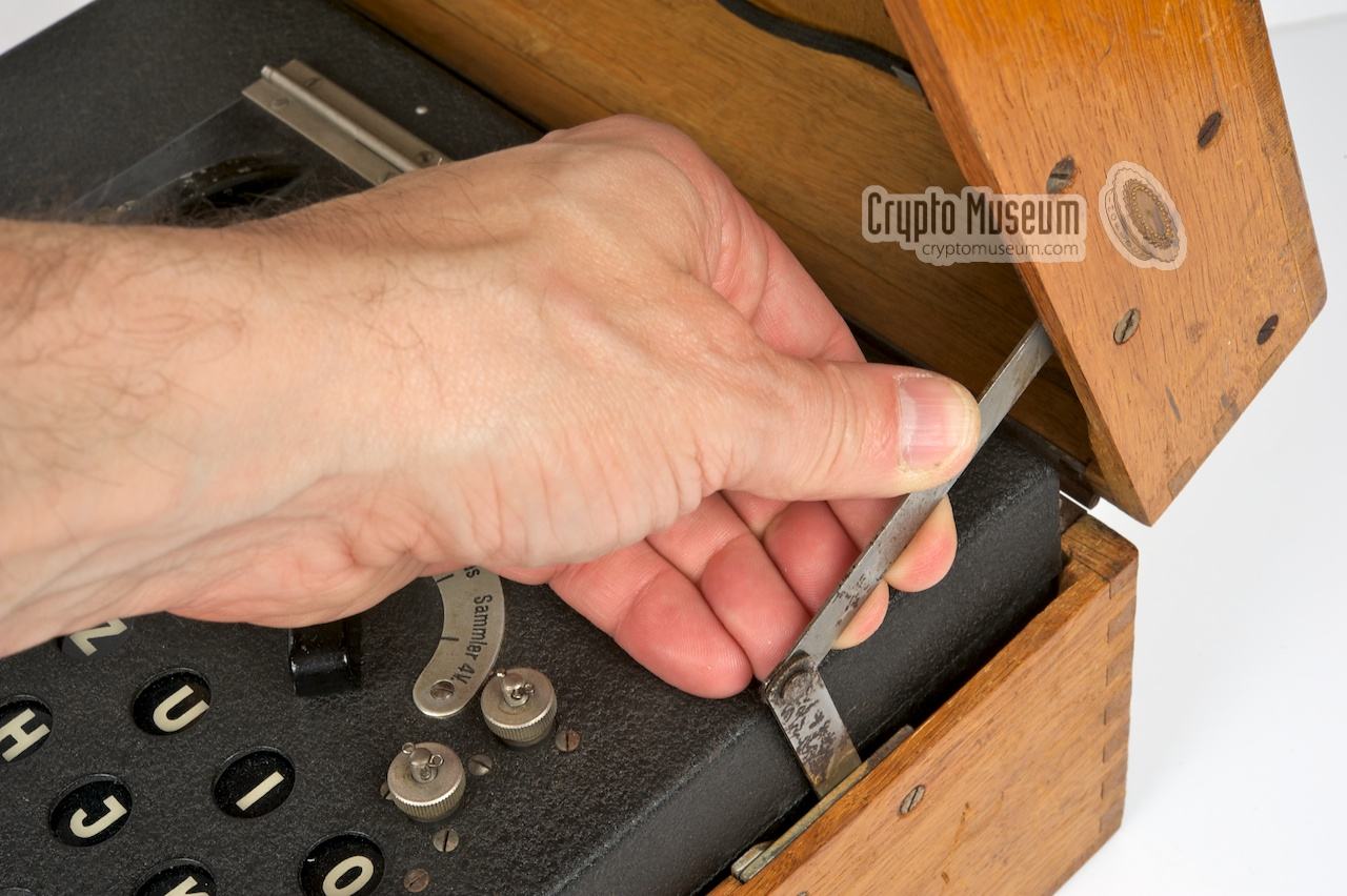
In order to replace the battery or to change the daily key (Grundstellung)
of the Enigma, the top lid of the machine needs to be opened. A rigged
bolt — with a red circle on top at either side of the lamp panel —
should be loosened in order to raise the hinged top lid and access the
interior.
|
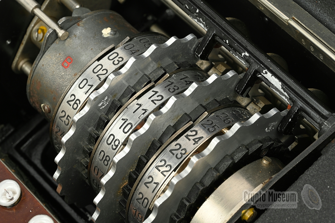
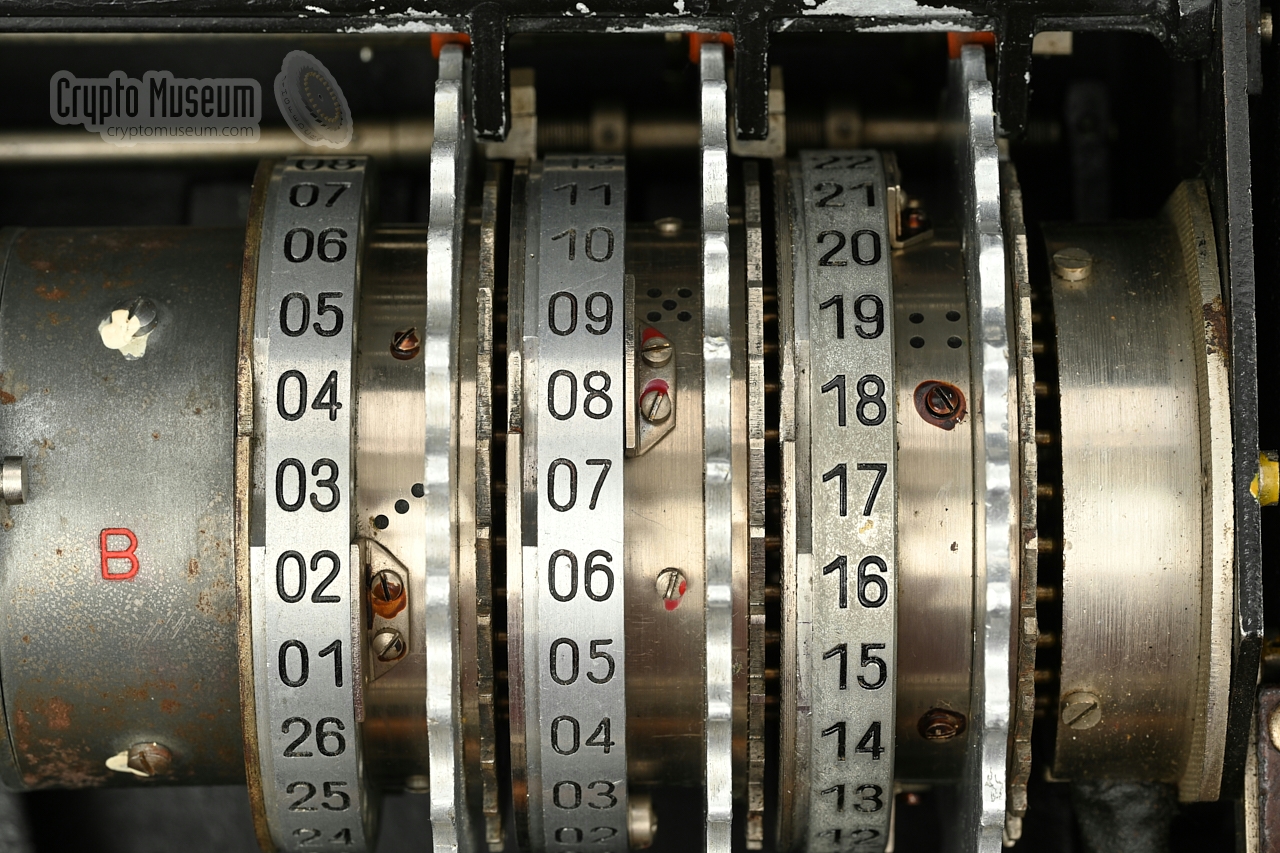
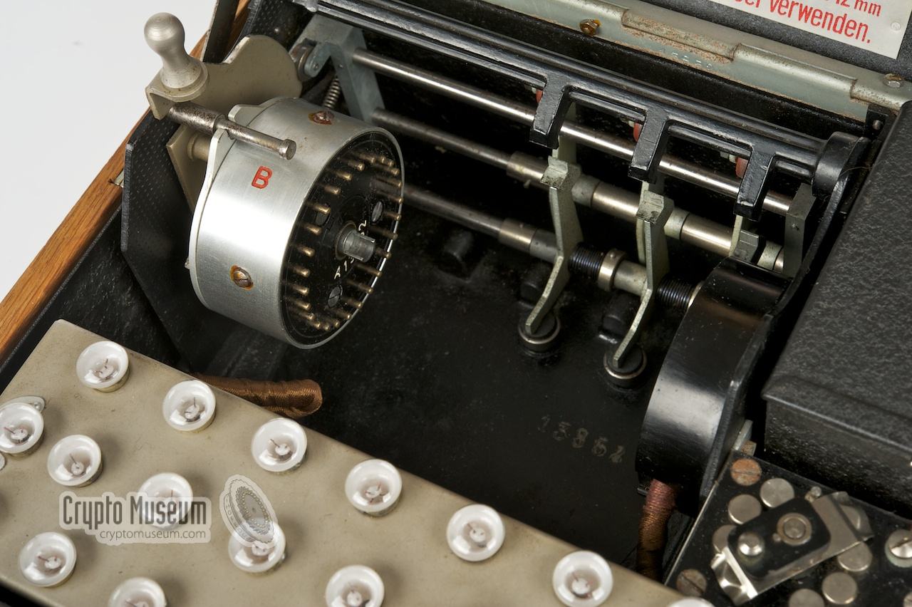
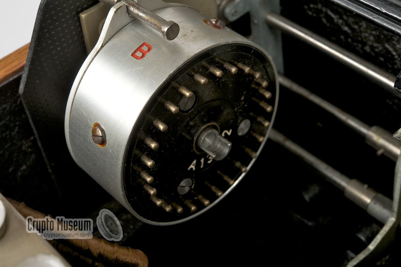
After raising the top lid, the rotor mechanism and the lamp panel are
exposed. The image on the right show the rotor stack, or drum.
At the right is the entry disc, or Eintrittswalze (ETW).
Left of the ETW are the three cipher rotors
and at the far left is the reflector (Umkehrwalze, UKW),
in the image on the right marked with a red B.
Just visible at the bottom right is the
interior of the power switch.
It is activated by the knob
that is attached to the top lid.
Just behind the power switch is a black box that holds the 4.5V
battery. The box is closed with a lid and a small lock.
|
|
|
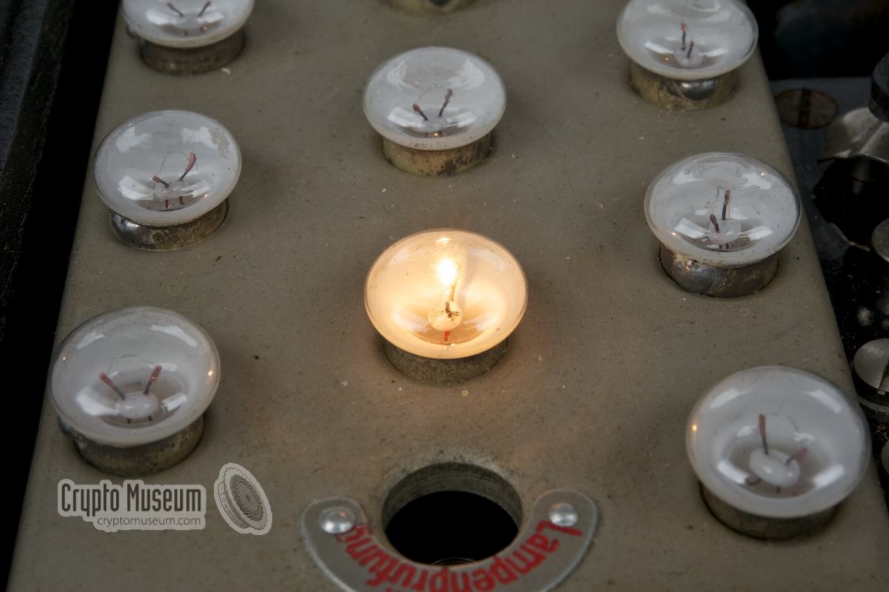
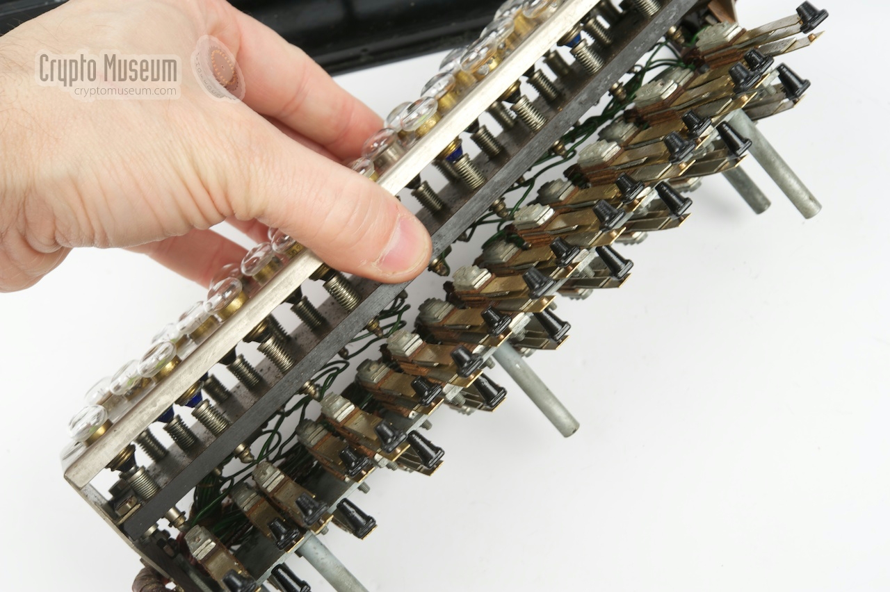
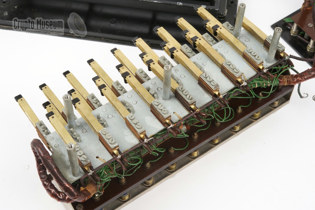
Below the rotors is the lamp panel.
It has 26 light blubs arranged in 3 rows. They are laid out in the
same order as the keyboard. Note that there are two additional
lamp sockets; one at either side of the middle row.
The extra socket at the right
is marked Lampenprüfung (lamp test). It can be used to
quickly test a lamp without typing on the
keyboard, simply by pressing it down.
Note that the light bulbs have an ordinary E10 fitting, but that
the glass bulb itself is flattened. Lamps of this time were commonly
used for bicycles and flash lights in those days.
Although it is possible to replace them by ordinary round bulbs,
this is not recommended as they will damage the
letter-film that is
mounted in the top lid. Never use ordinary light bulbs in an Enigma!
➤ More about the lamps
|
|
The extra socket at the left
is marked Kabelprüfung (cable test).
If a lamp it fitted in this socket, it can be used to quickly test
a patch cable. On the Steckerbrett
an extra single-ended socket is present at
either end of the middle row of plugs. The extra sockets are marked
with a red dot. Now hold the tick pin of one plug to the leftmost socket,
and the thin pin of the other one to the socket at the right.
If the wire is OK, the cable-test lamp
should light up.
Then test the other wire.
|
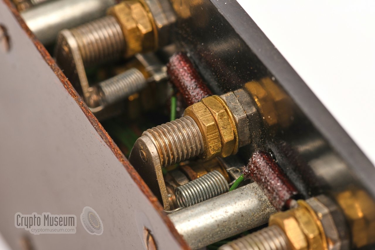
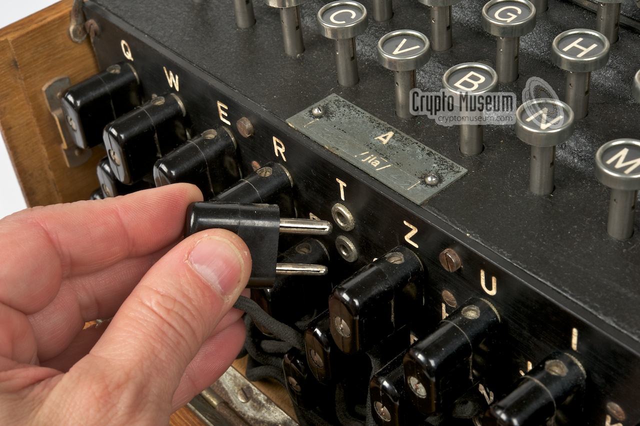
The double-ended Steckerbrett
had the advantage that it would swap the letters
in pairs and that the sockets had a built-in switch. If no swapping was
required, the cable could simply be left out. This greatly improved setup
time and reduced the chance of mistakes when setting the daily key.
Each Enigma comes with 12 cables: 10 to be used on the Steckerbrett and two
spares that are stored in the top lid of the case.
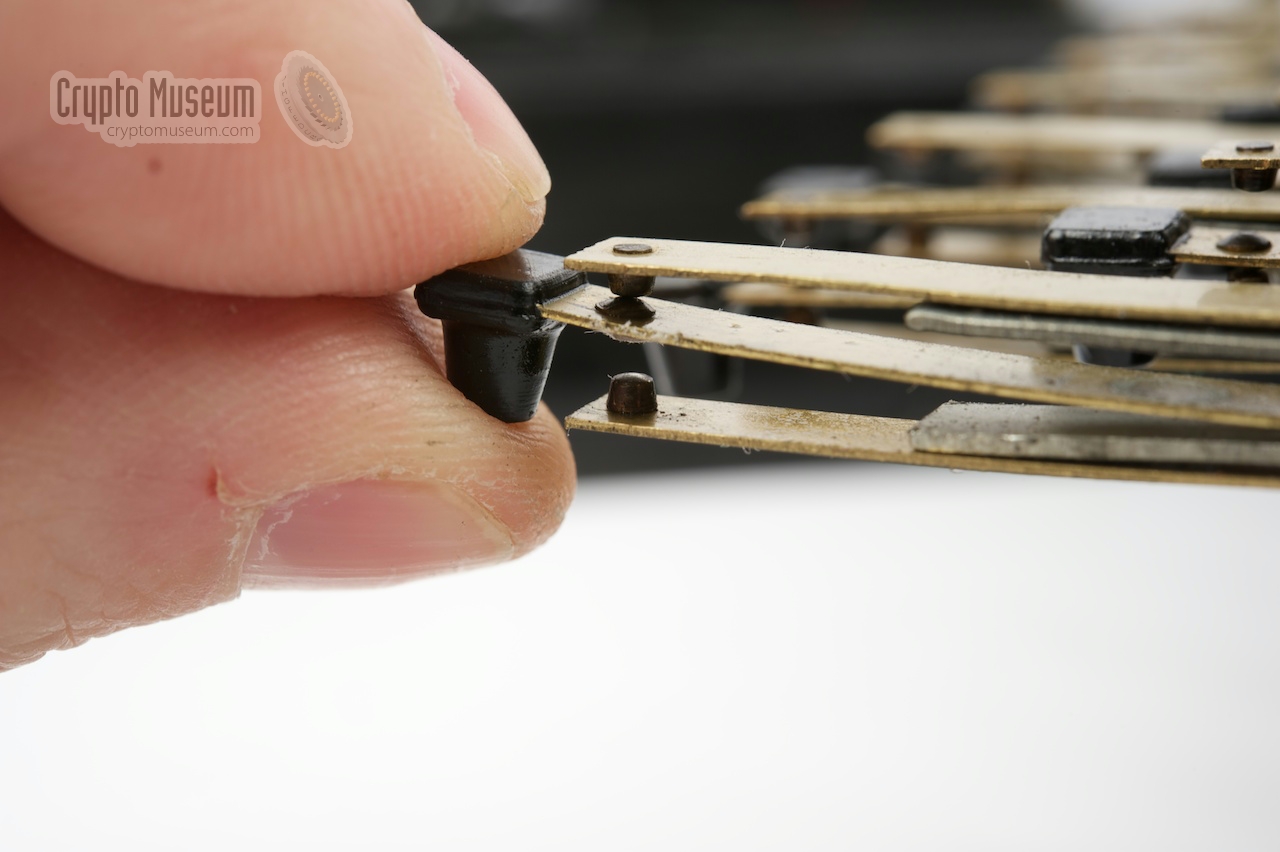
Each patch cable as a 2-pin plug at either side.
Each plug has a thick and a thin pin,
so that it can not be inserted
the wrong way around. The cable crosses the connection between
the plugs. The thick pin of one plug is connected to the other's thin one.
|
The image on the right shows a double-ended plug with a thick and a thin pin.
Swapping the letters in pairs means that if A is transposed to Z, the
reverse is also true: Z is transposed to A. This is known as
self-reciprocity.
Compared to a single-ended Steckerbrett,
this reduces the total number of
possible combinations significantly.
The same self-reciprocity was exploited by Gordon Welchman
when improving Turing's Bombe,
resulting in shorter Bombe-runs when breaking the Enigma's daily keys.
It effectively eliminated the Steckerbrett from the equasion.
|
|
|
With 26 letters, and hence 26 sockets on the Steckerbrett, a maximum of 13
patch cables could be installed. Any number of cables between 0 and 13 was
possible and the maximum number of combinations would have been reached when the
number of patch cables was different each day. In practice however, the
German operation procedure generally instructed the use of 10 cables.
➤ How the Steckerbrett works
➤ History of the Steckerbrett
|
WARNING —
Do not attempt to fit the patch cables from a
Naval Enigma
( Enigma M1, M2, M3 or M4)
into the Steckerbrett
of a standard Service Enigma. Although the pins have the same diameter, they
are approx. 4 mm longer, and may potentially damage the Steckerbrett when fully
inserted.
|
Sending a message with an Enigma machine involves the setting of
two cryptographic keys: (1) the daily key and (2) the
message key. Initially, the daily key was setup once a day
at midnight and was valid for 24 hours, hence its name.
Later in the war it was changed more frequently.
|
Setting the daily key (Grundstellung) involved a number of steps.
First the top lid of the machine should be opened in order to access
the interior.
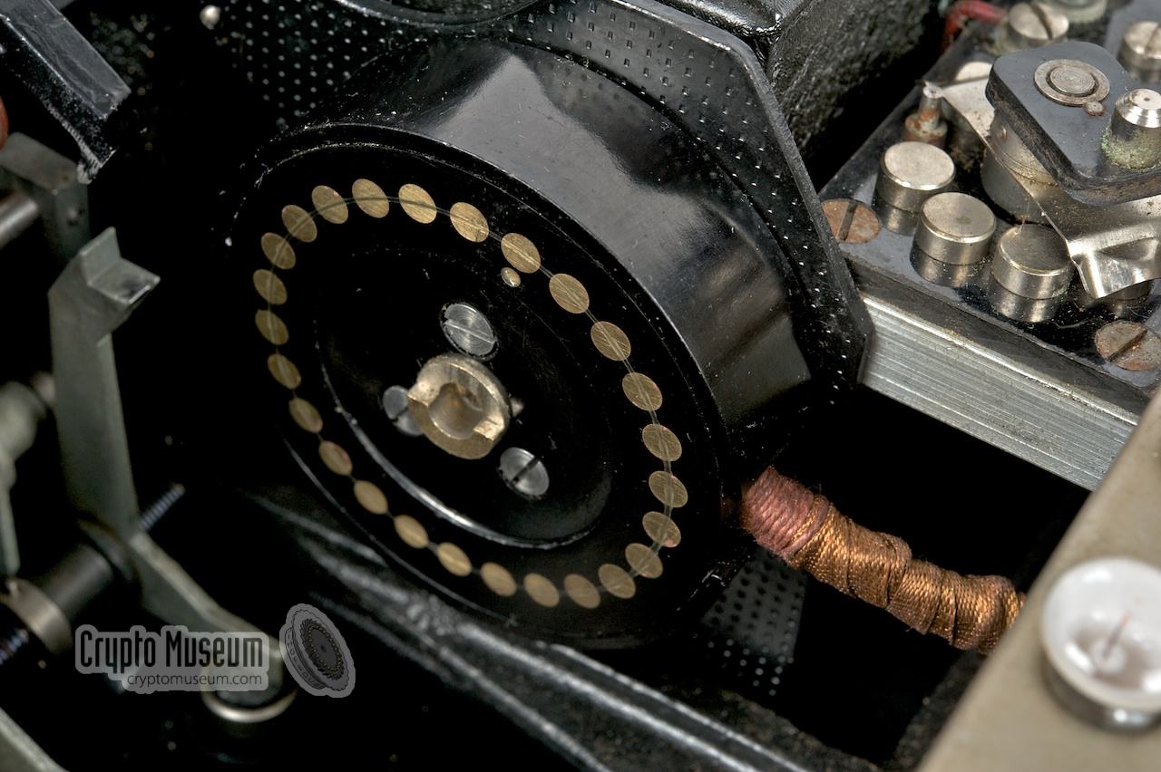
Next the UKW should be released
and shifted aside, so that the rotor-set
can be pressed together and
removed from the machine.
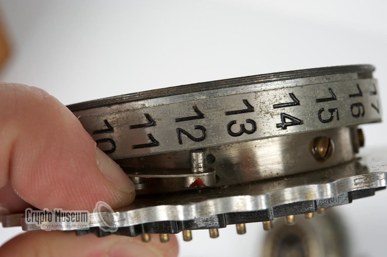
Now that the rotor-set is out of the machine,
the rotors are removed from the axle.
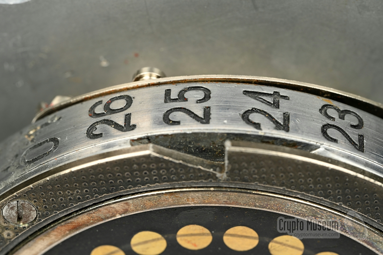
Next, the user would select the appropriate three rotors for the new
key and set the index ring as shown in the
codebook. The index ring can be released by lifting a
spring-loaded pin on its side.
|
|
|
The rotors are now put back on the spindle in the order given in the
codebook, and then placed in the machine again. After locking the
UKW again, the top lid can be closed. The rotors should now be set
to the required start position,
which is visible through the windows in the top lid.
Now that the rotors are setup correctly, the plugboard (Steckerbrett)
must be configured as per codebook. This involves removing all patch cables
from the plugboard and re-inserting them as indicated.
The machine is now ready for use.
For each new message, the operator had to select a unique message
key, consisting of three randomly selected letters.
The exact method for setting the message was changed several times
during the war and is beyond the scope of this page.
|
|
|
Wooden case with leather grip
|
|
|
Most Enigma I machines came in an oak wooden transport case – such as the one
shown in the image on the right – in which the machine was bolted to the bottom.
At the rear is a leather carrying strap. 1
More often than not, one of the four large bolts at the bottom is missing.
This type of enclosure is the most common one found with
Enigma cipher machines. They are usually made of solid oak wood, whilst the
top and bottom surfaces are covered with veneer.
|
|
|
-
Do not use the leather grip, as it will have
become fragile by now and is likely to break.
|
|
|
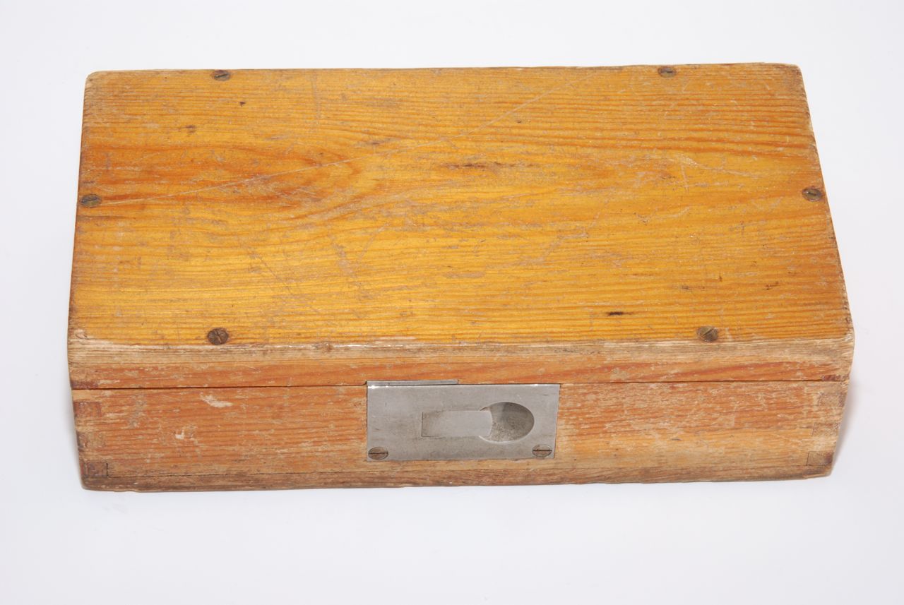
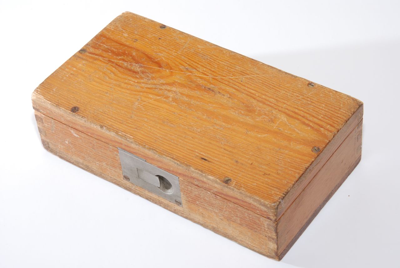
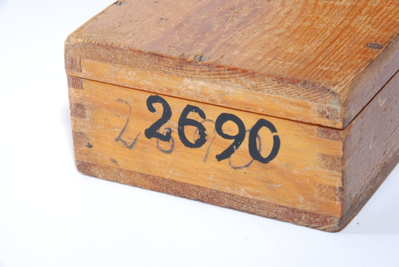
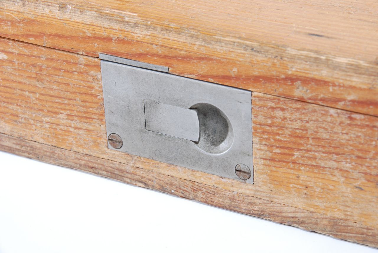
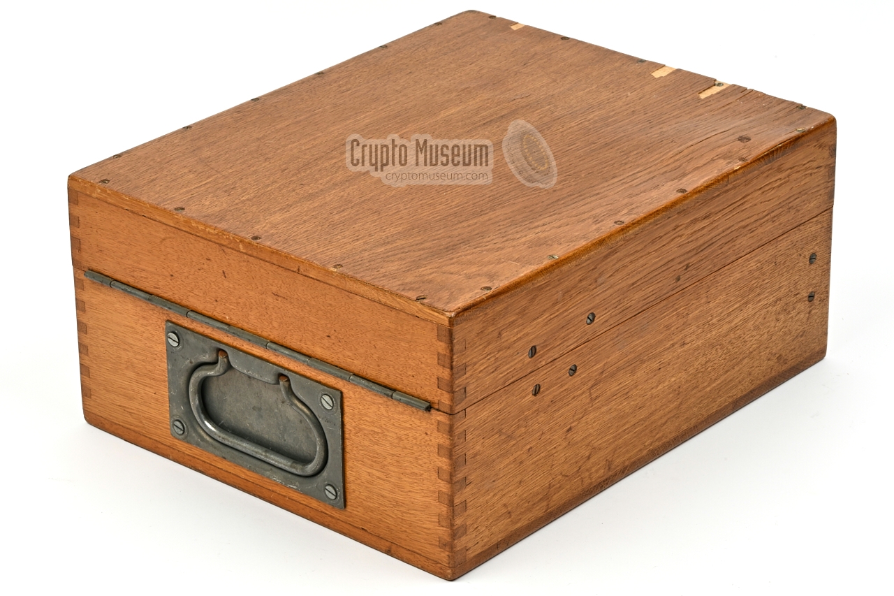
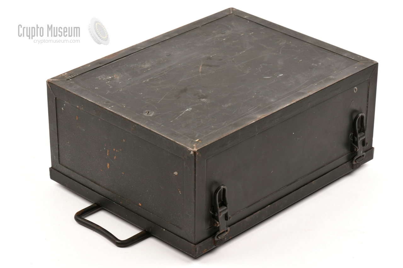
Wooden case with metal grip
|
|
|
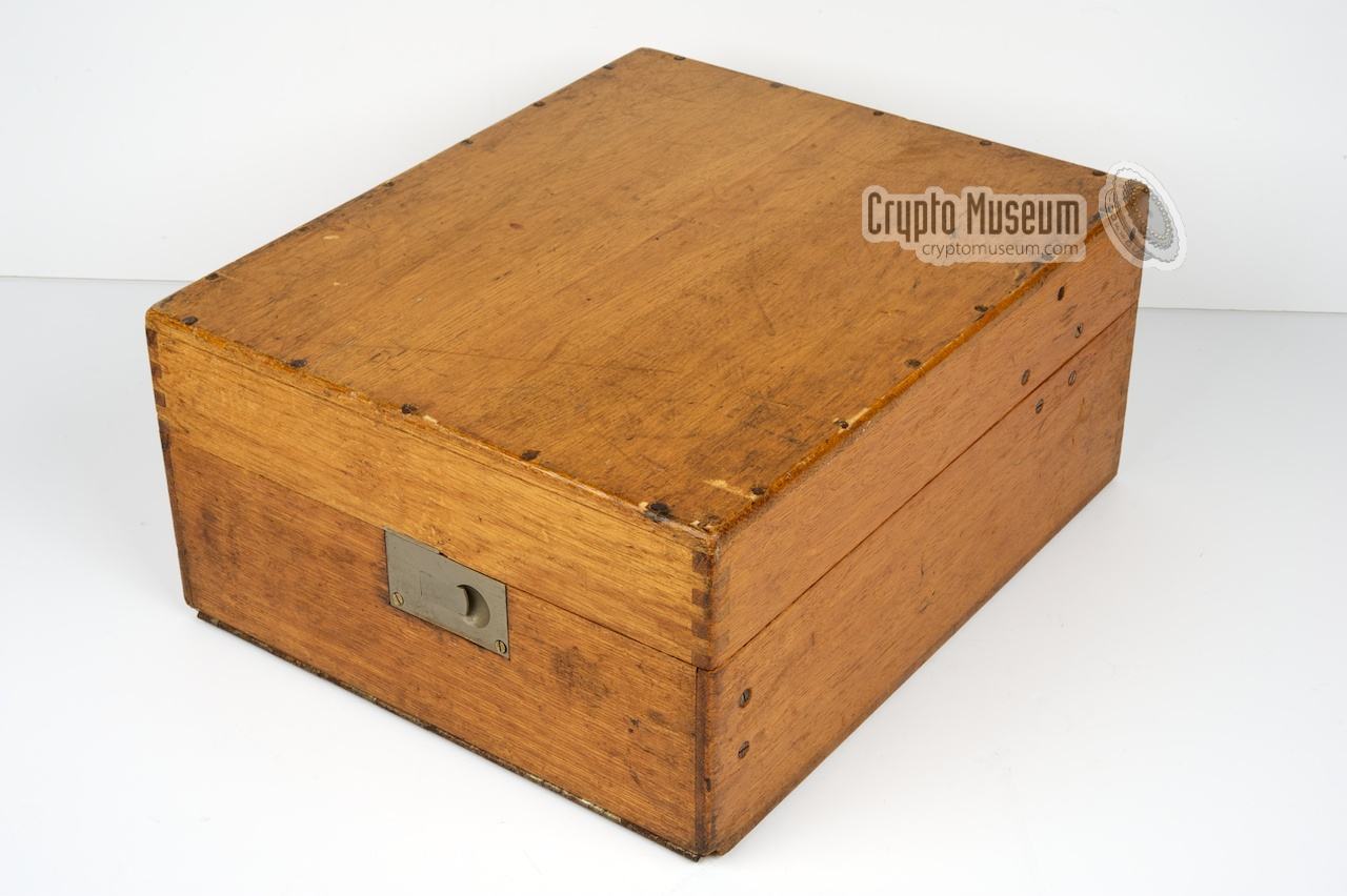
As an alternative to the above, there were also wooden cases with
a metal carrying handle at the rear, such as the one shown in the
image on the right. This type of enclosure was usually issued as a
replacement case for Enigma machines of which the original case
had been damaged.
This type of metal grip was also used on the wooden enclosures of
the Naval Enigma M1, M2, M3 and M4 machines.
It is currently unknown where these cases were manufactured.
|
|
|
|
|
Wooden case with canvas grip
|
|
|
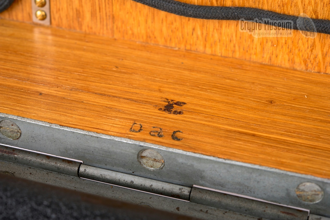
Please note that not all wooden boxes had a lether or metal carrying handle.
The wooden cases that were supplied by manufacturer
Ertel-Werk in München
had a canvas carrying strap fitted at the right side of the case,
as shown in the image on the right.
This type of case was used for (some) Enigma machines made by
Ertel,
but was also supplied as replacement case for machines from other
manufacturers of which the original wooden case had been damaged.
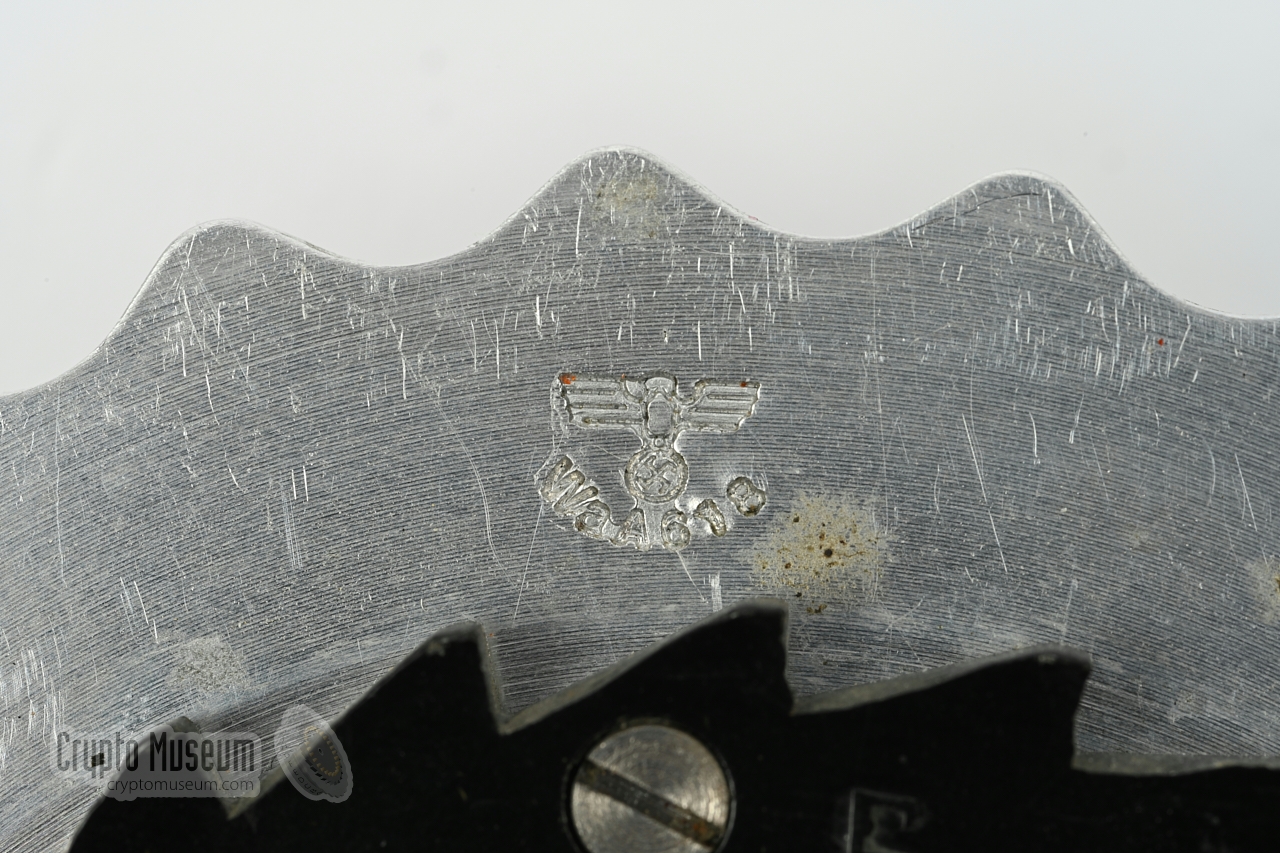
The manufacturer code (bac) is usually
present inside the top lid.
➤ More about Ertel-Werk
|
|
|
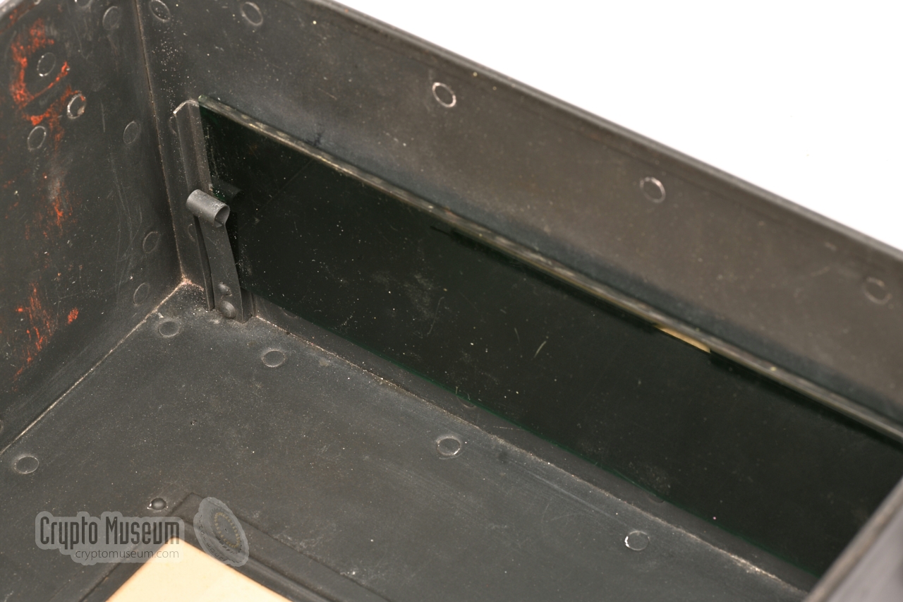
Apart from wooden cases, Ertel-Werk
also made Panzerholz cases,
which consist of a bottom panel and a removable dust cover. The machine is
bolted to the bottom panel and a metal sliding panel is present at the front to
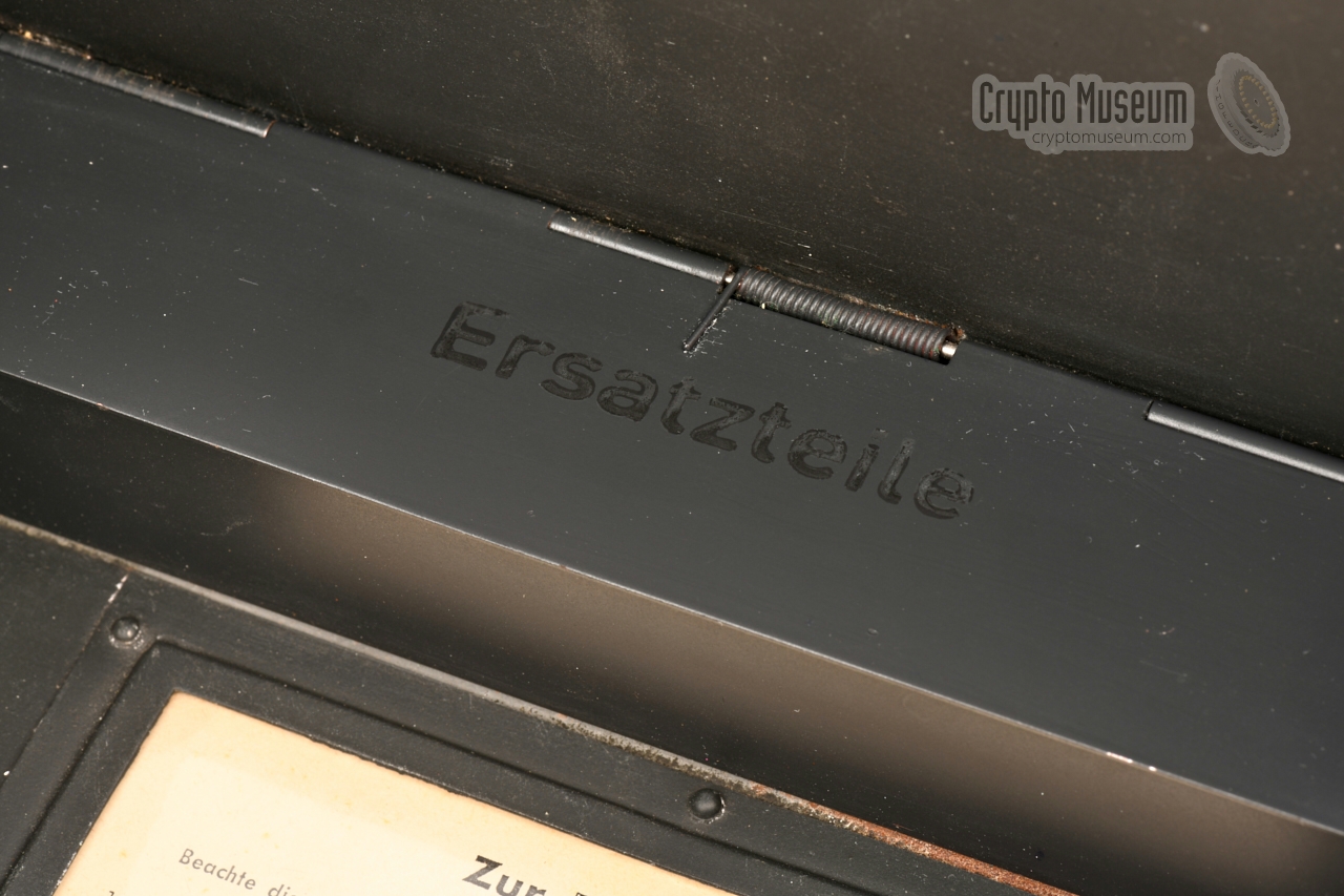
keep the plugs in place. Inside the dust cover is a
compartment with a hinged spring-loaded lid,
inside which the spare light bulbs and patch cables are stowed.
Cases of this type 1 are often erroneously attributed to the German Air
Force (Luftwaffe). Although they were used by the Luftwaffe, they
were also used by the German Army (Heer).
➤ More about Ertel-Werk
|
|
|
-
Note that these cases are only suitable for Enigma machines made by
Ertel-Werk (bac),
as these are 2 mm less wide than the machines from other
manufacturers. Mounting another manufacturer's Enigma in an Ertel Panzerholz
case, is likely to damage the metal lid of the
machine when placing the dust cover over it.
|
|
Inside the top lid of the wooden Enigma storage case, is usually a
screen-printed plate with maintenance instructions.
This plate can be made of aluminium, celluloid or resopal. In the example
above, it is screen-printed in black on white resopal. The text translates
as follows:
|
Attention!
Refer to the operating instructions for the Cipher Machine (H. Dv. g. 13)
- For cleaning the rotor contacts, rotate each rotor back and forth individually.
- For cleaning the keyboard contacts, press each key individually before turning
on the power, and release it quickly, whilst keeping one of the other keys depressed.
- When setting the rotor positions, check the windows to ensure that each rotor
is correctly locked into position.
- The unreversible two-pin plugs should be inserted as far as possible.
The wooden flap at the front should then be closed, as otherwise 3 lamps may
be lit simultaneously.
- If no lamp is lit when a key is pressed, check the battery, its contact strips,
its connections to the power switch and the power switch itself.
- If one or more lamps are not lit when pressing a key, check the corresponding
lamps, their fittings, the patch cables, the sockets on the patch panel, the
shorting bars behind the sockets, the rotor contacts, the switch contacts under
the key that was pressed, and the normally closed contact of the corresponding key.
Remove any dirt or oxide (see also point 2).
- Rotor axle and spring-loaded rotor contacts should be held clean and
– like all other moving parts – should be treated with resin-free and acid-free
oil. The fixed rotor contacts should be polished with polish paper each 6-8 weeks,
and cleaned with an oiled cloth. The keyboard contacts, the lamp contacts and the
shorting bars should be protected against oil.
- Key settings are specified with either numbers or letters.
For conversion between numbers and letters or vice versa, use the following table:
|
The Enigma I is powered by a standard 4.5V Wehrmacht battery,
such as the one shown in the image on the right.
It must be installed in the black battery compartment in the rear
right corner of the machine, below a hinged lid.
|
|
|
During WWII, the Germans made several attempts to
make the Enigma more secure.
In July 1944, the German Luftwaffe came up
with a smart device called Enigma Uhr, which was
introduced without any prior warning.
It was attached to the side of an Enigma I — hanging off
the side of the wooden case — and was
connected directly to the Steckerbrett.
➤ More information
|
|
|
Initially, the Enigma I was supplied with three cipher wheels (rotors)
marked I, II and III. They could be placed in the machine in 6 possible orders.
On 15 December 1938, two additional rotors were introduced, marked IV and V.
Three of these five rotors can be placed in the machine in 60 possible orders
(5 × 4 × 3).
➤ More information
|
|
|
During WWII, the Enigma I was equipped with reflector UKW-C
or UKW-D. The wiring of these reflectors was fixed.
In an attempt to improve the security of the Enigma, the German Air Force
(Luftwaffe) introduced a field-rewirable reflector named UKW-D.
UKW-D was introduced in Janury 1944, and a special variant was
made for use with the Naval machines M1, M2, M3 and M4.
➤ More information
|
|
|
|
Below is the standard wiring for each of the 5 cipher rotors,
the ETW and all three known
UKWs. UKW-A was used before WWII [1]. UKW-B was the standard
reflector during the war, and UKW-C was only used temporarily during the war.
The wiring of rotors I-V is identical to the wiring of the
first 5 rotors of the Enigma M3 1 (used by
the Kriegsmarine) and the U-Boot Enigma M4.
|
|
Rotor
|
ABCDEFGHIJKLMNOPQRSTUVWXYZ
|
Notch
|
Turnover
|
#
|
|
|
|
ETW
|
ABCDEFGHIJKLMNOPQRSTUVWXYZ
|
|
|
|
|
I
|
EKMFLGDQVZNTOWYHXUSPAIBRCJ
|
Y
|
Q
|
1
|
|
II
|
AJDKSIRUXBLHWTMCQGZNPYFVOE
|
M
|
E
|
1
|
|
III
|
BDFHJLCPRTXVZNYEIWGAKMUSQO
|
D
|
V
|
1
|
|
IV
|
ESOVPZJAYQUIRHXLNFTGKDCMWB
|
R
|
J
|
1
|
|
V
|
VZBRGITYUPSDNHLXAWMJQOFECK
|
H
|
Z
|
1
|
|
UKW-A 2
|
EJMZALYXVBWFCRQUONTSPIKHGD
|
|
|
|
|
UKW-B
|
YRUHQSLDPXNGOKMIEBFZCWVJAT
|
|
|
|
|
UKW-C
|
FVPJIAOYEDRZXWGCTKUQSBNMHL
|
|
|
|
|
-
Enigma M1, M2 and M3 are electrically identical.
-
Wiring recovered by Philip Marks and Frode Weierud in 2000 [1].
|
|
In 1945, immediately after WWII, some captured Enigma-I machines were
used by the the former Norwegian Police Security Service:
Overvaakingspolitiet.
They modified the rotor wiring
and the wiring of the Umkehrwalze (UKW, reflector).
The wiring of the Eintrittzwalze (ETW, entry disc) and the position
of the turnover notches on the rotors were left unaltered.
A machine that is modified in this way, is often referred to as
Norway Enigma or Norenigma as coined by Frode Weierud
in 2001, in order to discriminate between the standard and the modified wiring [2].
|
|
Rotor
|
ABCDEFGHIJKLMNOPQRSTUVWXYZ
|
Notch
|
Turnover
|
#
|
|
|
|
ETW
|
ABCDEFGHIJKLMNOPQRSTUVWXYZ
|
|
|
|
|
I
|
WTOKASUYVRBXJHQCPZEFMDINLG
|
Y
|
Q
|
1
|
|
II
|
GJLPUBSWEMCTQVHXAOFZDRKYNI
|
M
|
E
|
1
|
|
III
|
JWFMHNBPUSDYTIXVZGRQLAOEKC
|
D
|
V
|
1
|
|
IV
|
FGZJMVXEPBWSHQTLIUDYKCNRAO
|
R
|
J
|
1
|
|
V
|
HEJXQOTZBVFDASCILWPGYNMURK
|
H
|
Z
|
1
|
|
UKW
|
MOWJYPUXNDSRAIBFVLKZGQCHET
|
|
|
|
|
Device Cipher machine Brand Enigma Manufacturer ChiMaAg, H&R, K&K, Olympia, Ertel, Atlas Country Germany Users German Army (Wehrmacht) German Air Force (Luftwaffe), Railway Rotors 3 (from a set of 5) Turnovers 1 per rotor Reflector Fixed (type B or C) Wiring see above Stepping Standard (Enigma stepping) Plugboard yes Extras Green sunlight filter
|
|
The machine is known by the following names:
|
- Ch.11a
- Ch.11f
- Enigma I
- Reichswehr Enigma
- Wehrmacht Enigma
- Heeres Enigma
- Army Enigma
- Service Enigma
- Army/GAF Enigma
- 3-wheel Enigma
- 3-rotor Enigma
- 3-wheeler
|
The official name, used by the German Army in correspondence with
manufacturer Heimsoeth und Rinke, is Enigma I (Roman number 1),
Ch.11a or Ch.11f, although these names were not used by the operators.
|
|
|
|
Any links shown in red are currently unavailable.
If you like the information on this website, why not make a donation?
© Crypto Museum. Created: Tuesday 11 August 2009. Last changed: Tuesday, 30 January 2024 - 12:43 CET.
|
 |

|
|
|
| |